Communication apparatus, communication method, program for controlling communication apparatus, storage medium storing program
- Summary
- Abstract
- Description
- Claims
- Application Information
AI Technical Summary
Benefits of technology
Problems solved by technology
Method used
Image

Examples
first embodiment
[0037]The first embodiment of the present invention will be described hereinafter.
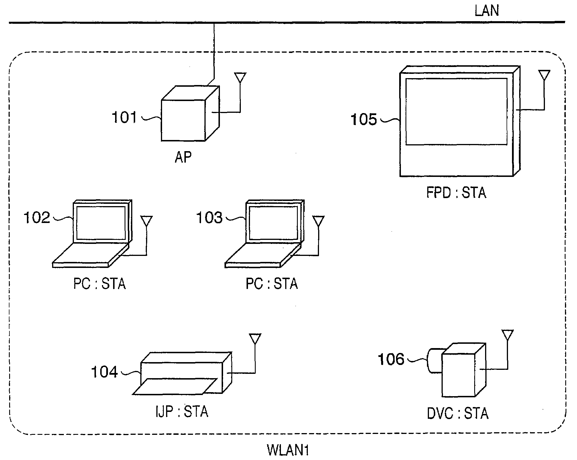
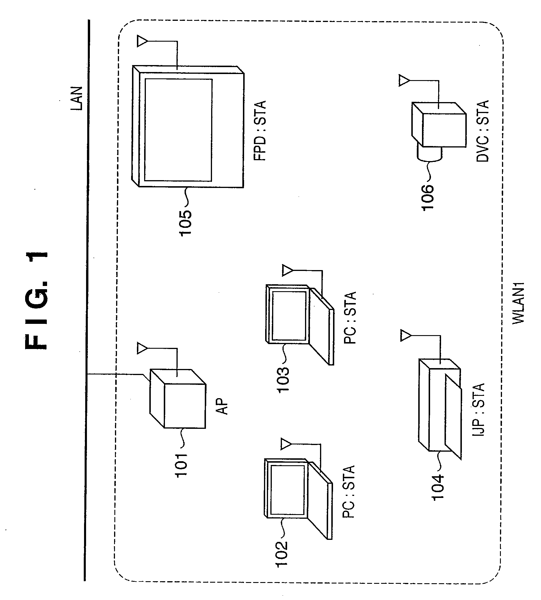
[0038]FIG. 1 is a diagram showing the configuration of a wireless LAN (WLAN) 1 as a first wireless network. Reference numeral 101 denotes an access point (AP). Reference numerals 102 and 103 denote personal computers (PCs). Reference numeral 104 denotes an ink-jet printer (IJP). Reference numeral 105 denotes a flat panel display (FPD). Reference numeral 106 denotes a digital video camera (DVC). Note that the AP 101, PC 102, PC 103, IJP 104, FPD 105, and DVC 106 comprise a wireless communication function compliant with the IEEE802.11 standard and the IEEE802.11e standard. The AP 101 creates and manages a wireless network (WLAN1) by an access point function. The PC 102, PC 103, IJP 104, FPD 105, and DVC 106 associate themselves in the WLAN1 created and managed by the AP 101 by a station function. The AP 101 also relays a wired network LAN, and stations that associate themselves in the WLAN1 can communicate
second embodiment
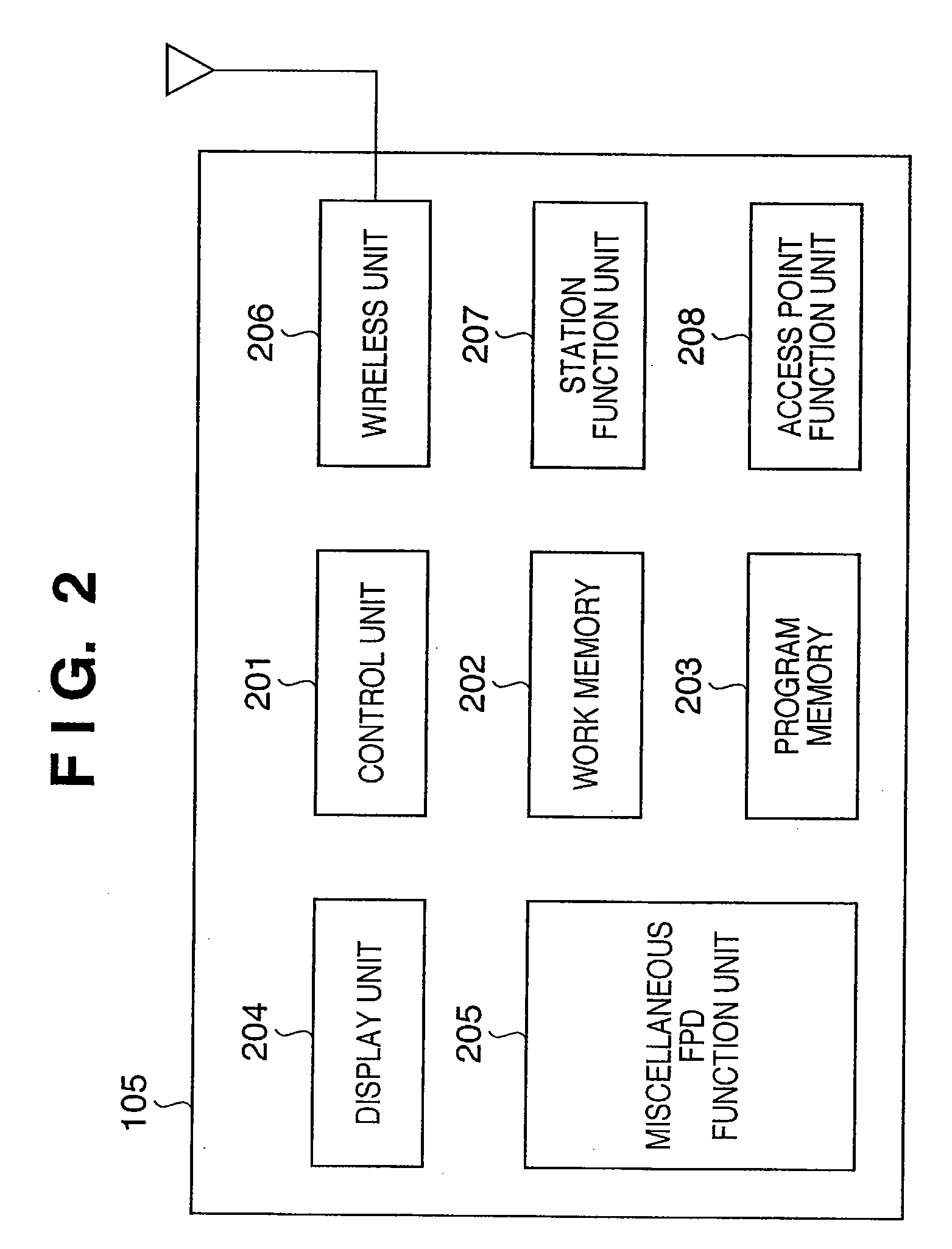
[0077]The second embodiment of the present invention will be described hereinafter. The embodiment will explain a process that is executed after a traffic communication of the video data 407 in FIG. 4. That is, the processing according to the embodiment is executed after the FPD 105 transmits the playback_preparation_completion data (F503) in FIG. 5A, receives the traffic of the video data 407, and plays back the video data 407. If the AP 101 denies guarantee of the QoS for the traffic of the video data 407 in step F502 in FIG. 5A, the processes in step F503 and subsequent steps are executed according to the first embodiment. According to the embodiment, the arrangements of the FPD 105 and DVC 106 are the same as per FIGS. 2 and 3.
[0078]FIG. 12 is a flowchart executed until the FPD 105 creates a second wireless network (WLAN2). The flow control is implemented when the control unit 201 of the FPD 105 controls the wireless unit 206, the station function unit 207, and the access point con
third embodiment
[0091]The third embodiment of the present invention will be described hereinafter. Again, according to the embodiment, the arrangements of the FPD 105 and DVC 106 are the same as per FIGS. 2 and 3. The embodiment will describe an example in which the FPD 105 checks if a communication at the requested transmission data rate can be made in the WLAN1, and creates a new network depending on the result of the check.
[0092]FIG. 15 is a flowchart that is executed until the FPD 105 creates a second wireless network (WLAN2). The flow control is implemented when the control unit 201 of the FPD 105 controls the wireless unit 206, a station function unit 207, and an access point function unit 208 in accordance with the programs stored in the program memory 203. The flow control of FIG. 15 starts immediately after, e.g., the FPD 105 associates itself in the WLAN1 or after the FPD 105 receives the playback_preparation_request data 401 from the DVC 106.
[0093]The FPD 105 executes surplus band search pr
PUM
 Abstract
Description
Claims
Application Information
 - R&D Engineer
- R&D Manager
- IP Professional
- Industry Leading Data Capabilities
- Powerful AI technology
- Patent DNA Extraction
Browse by: Latest US Patents, China's latest patents, Technical Efficacy Thesaurus, Application Domain, Technology Topic.
© 2024 PatSnap. All rights reserved.Legal|Privacy policy|Modern Slavery Act Transparency Statement|Sitemap