Surface light source device and display apparatus
a light source device and surface technology, applied in lighting and heating devices, planar/plate-like light guides, instruments, etc., can solve the problems of limited options and the tendency to widen the actual viewing angle greater than the desired rang
- Summary
- Abstract
- Description
- Claims
- Application Information
AI Technical Summary
Benefits of technology
Problems solved by technology
Method used
Image

Examples
first preferred embodiment
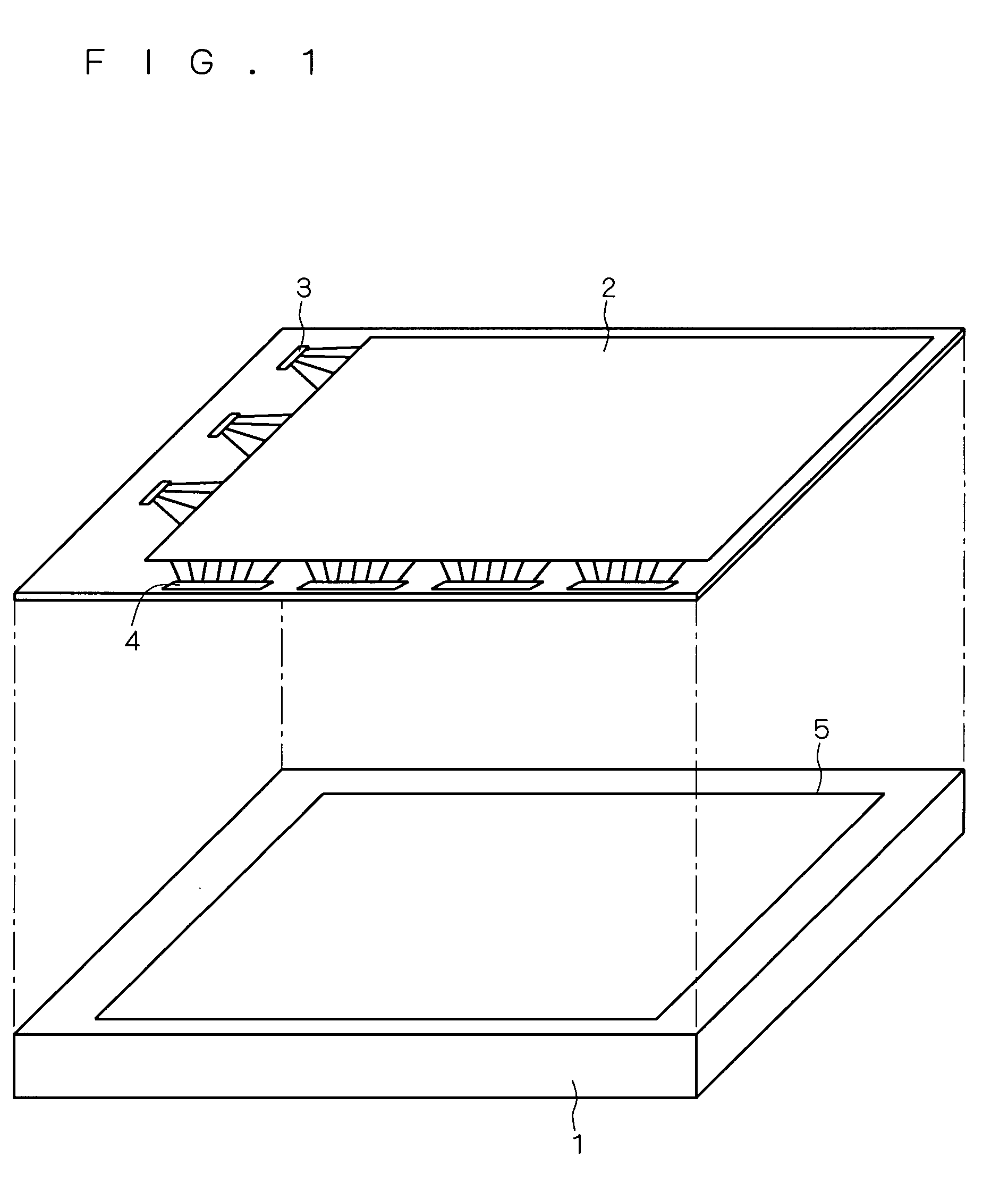
[0022]The following description is given on the assumption that display apparatuses according to the invention are liquid crystal display apparatuses. FIG. 1 is an exploded perspective view showing an example of the outline configuration of a liquid crystal display apparatus of the present preferred embodiment. As shown in the figure, the liquid crystal display apparatus of the present preferred embodiment includes a surface light source device 1, a liquid crystal panel 2, gate drivers 3, and source drivers 4.
[0023]The surface light source device 1 has a main surface from which light is emitted. In the present preferred embodiment, light from the main surface of this surface light source device 1 illuminates the liquid crystal panel 2 through an opening 5. The surface light source device 1 is placed on the back surface side of the liquid crystal panel 2 and irradiates the back surface side of the liquid crystal panel 2 with light. The liquid crystal panel 2 as a display device is provi
second preferred embodiment
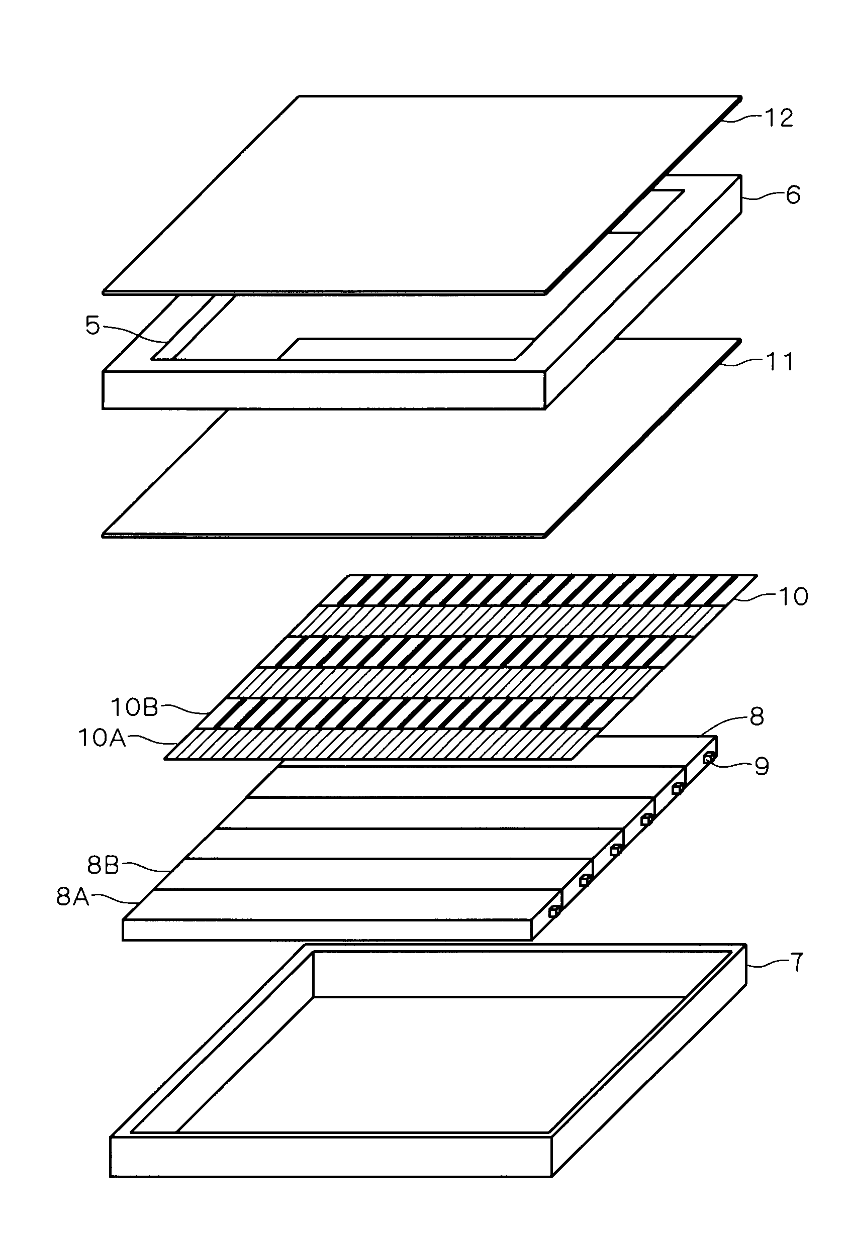
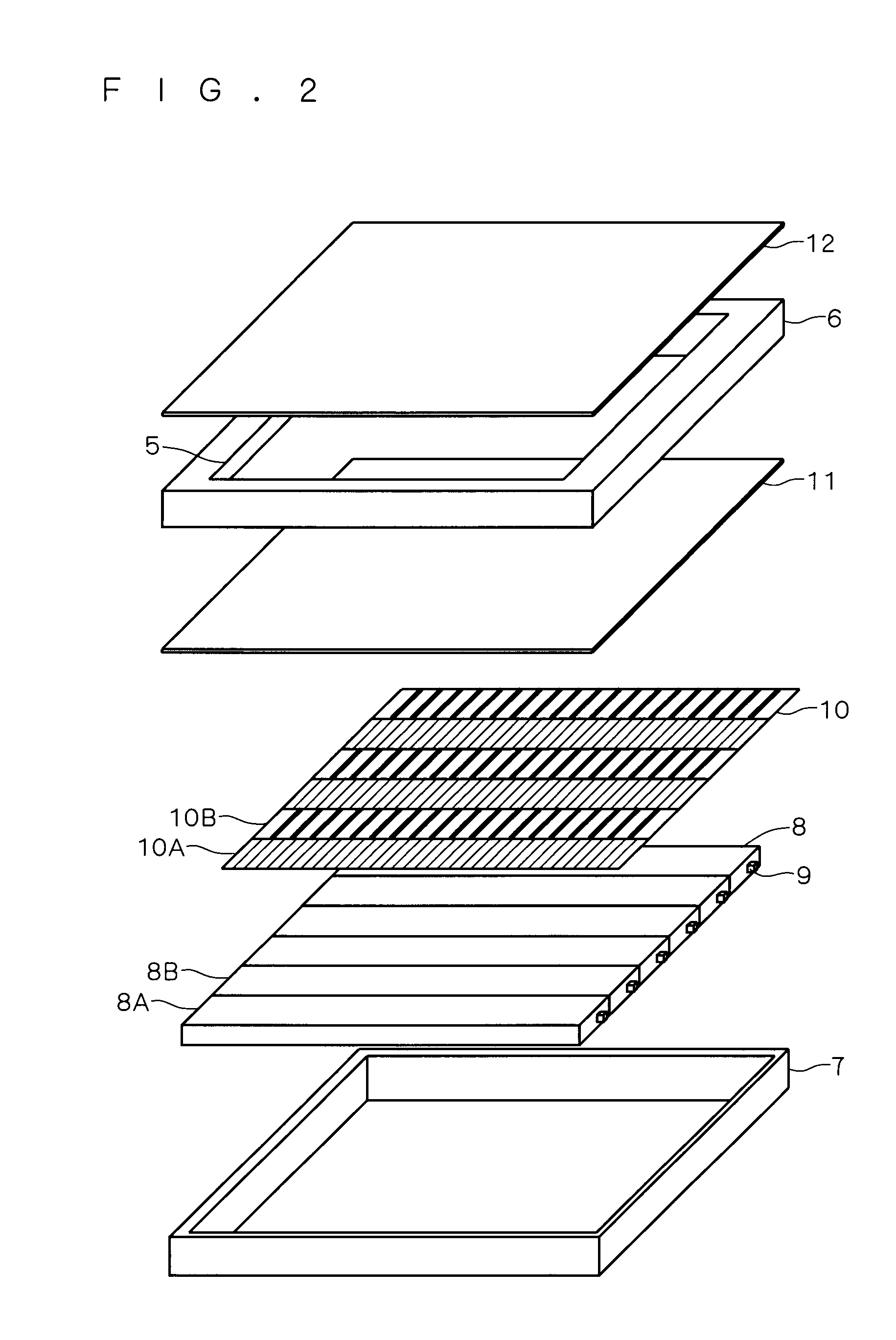
[0065]FIG. 11 is a plan view showing an example of the essential configuration of the surface light source device 1 according to another preferred embodiment of the invention. This figure corresponds to FIG. 3 of the first preferred embodiment. Hereinafter, the components similar to those described in the first preferred embodiment are designated by the same reference numerals or characters.
[0066]As in the first preferred embodiment, an optical film is provided on the exit surface side of the light guide plates 8. In the present preferred embodiment, the optical film further includes a diffusion film 20 that is alternately arranged with the light-shield slit film 10 and that diffuses light emitted from the light guide plates 8.
[0067]As shown in FIG. 11, in the present preferred embodiment, the light-shield slit film 10 is provided along the light guide plates 8A, and the diffusion films 20 is provided along the light guide plates 8B. A certain range of angles of the light-shield slit f
PUM
 Abstract
Description
Claims
Application Information
 - R&D Engineer
- R&D Manager
- IP Professional
- Industry Leading Data Capabilities
- Powerful AI technology
- Patent DNA Extraction
Browse by: Latest US Patents, China's latest patents, Technical Efficacy Thesaurus, Application Domain, Technology Topic.
© 2024 PatSnap. All rights reserved.Legal|Privacy policy|Modern Slavery Act Transparency Statement|Sitemap