Integrated distance measuring equipment and transponder system and method

a technology of integrated distance measuring equipment and transponder system, which is applied in the direction of instruments, measurement devices, and using reradiation, can solve the problems of large total system weight, high cost, and large coaxial cabling requirements, and achieve the effect of cost advantag

Active Publication Date: 2008-10-02
HONEYWELL INT INC
View PDF5 Cites 61 Cited by
  • Summary
  • Abstract
  • Description
  • Claims
  • Application Information

AI Technical Summary

Benefits of technology

The invention relates to a combination of different types of communication devices called transponders and domechanisms used on airplanes. These devices are designed with special features like transmitting signals at specific frequencies or wavelengths, allowing multiple components to work together more efficiently. They share certain parts of their circuitry instead of requiring separate circuits. Additionally, they have a unique design where only one part needs to operate while other parts are being controlled by another device. Overall, this technology makes it easier and cheaper to implement new technologies such as wireless networks.

Problems solved by technology

The technical problem addressed by this patent is reducing the size and complexity of current transponder and distance measurement equipment used in airplanes without compromising its performance or efficiency.

Method used


Image

  • Integrated distance measuring equipment and transponder system and method
  • Integrated distance measuring equipment and transponder system and method
  • Integrated distance measuring equipment and transponder system and method

Examples


Embodiment Construction

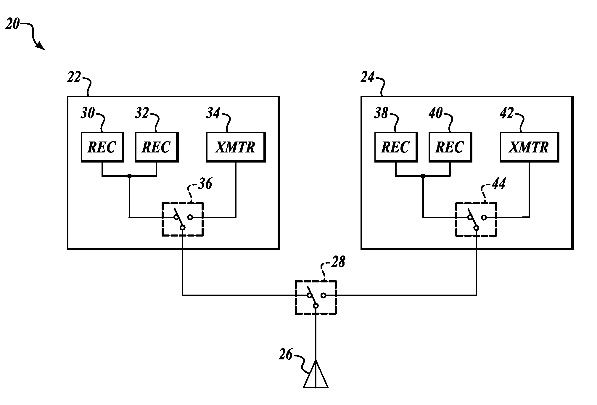
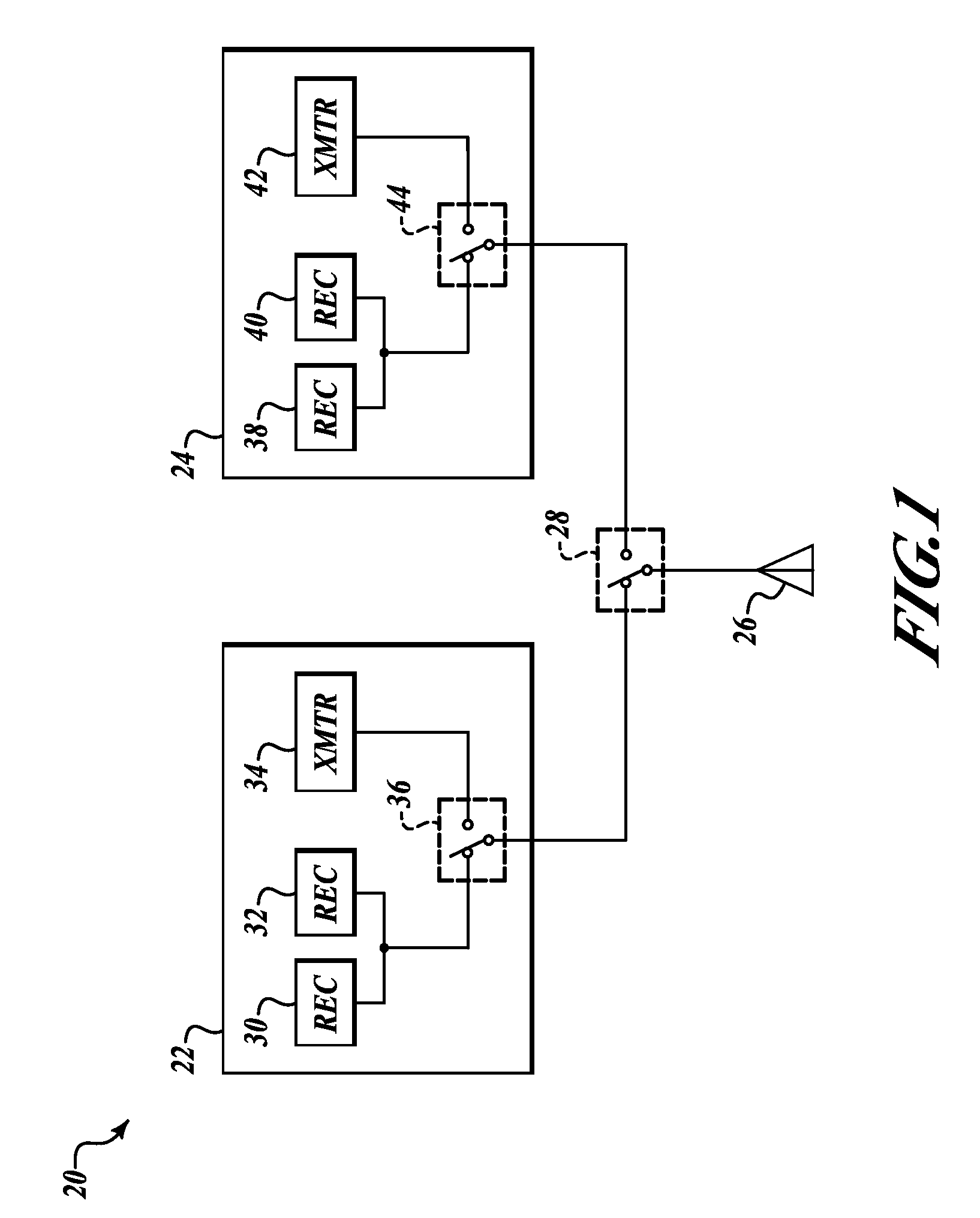
[0011]FIG. 1 is a block diagram of a combined transponder (XPDR) and distance measuring equipment (DME) system 20 for use in an aircraft formed in accordance with an embodiment of the invention. In an example embodiment, the system 20 is a redundant system that includes a first line replaceable unit (LRU) 22 and a second LRU 24 that are connected to an antenna 26 through an LRU1 / LRU2 switch 28. In an example embodiment, the antenna 26 is an L-band blade antenna. Each LRU 22 and 24 includes an integrated DME and XPDR transceiver system. The first LRU 22 includes a receiving path having a first receiver 30 and a second receiver 32. The first LRU 22 also includes a transmitter 34 linked to a TX / RX switch 36 that selectively connects either the transmitter 34 or the receivers 30 and 32 to a first lead of the LRU1 / LRU2 switch 28.

[0012]In similar fashion, the second LRU 24 includes a receiving path having a first receiver 38 and a second receiver 40. The second LRU 24 also includes a t


PUM


Abstract

A combined transponder and DME system for use in an aircraft. An L Band transmitter is shared between transponder and DME.

Description


Claims


Application Information

Patent Timeline
Owner HONEYWELL INT INC
Why Eureka
Try Eureka