High frequency receiving apparatus

a high frequency receiving and receiving device technology, applied in the field of high frequency receiving devices, can solve the problems of cost and inhibiting price reduction, and the conventional high frequency receiving device of the tuner is described, and achieve the effects of reducing size, high frequency, and price reduction

Inactive Publication Date: 2008-11-27
SHARP KK
View PDF1 Cites 0 Cited by
  • Summary
  • Abstract
  • Description
  • Claims
  • Application Information

AI Technical Summary

Benefits of technology

The technical effect of this patented invention is to create an improved high-frequency receiver with smaller dimensions while also reducing its cost compared to previous designs.

Problems solved by technology

The technical problem addressed in this patent is how to reduce the overall size of a high frequency receiving device while maintaining its performance level. Specifically, it addresses the issue of interference between different types of signals when transmitting terrestriast and satellite broadcast signals through separate partitions located outside the housing of the device. Additionally, the patent seeks to provide a solution where multiple components can be housed within the same cabinet without increasing their size.

Method used


Image

  • High frequency receiving apparatus
  • High frequency receiving apparatus
  • High frequency receiving apparatus

Examples


first modification

[0039

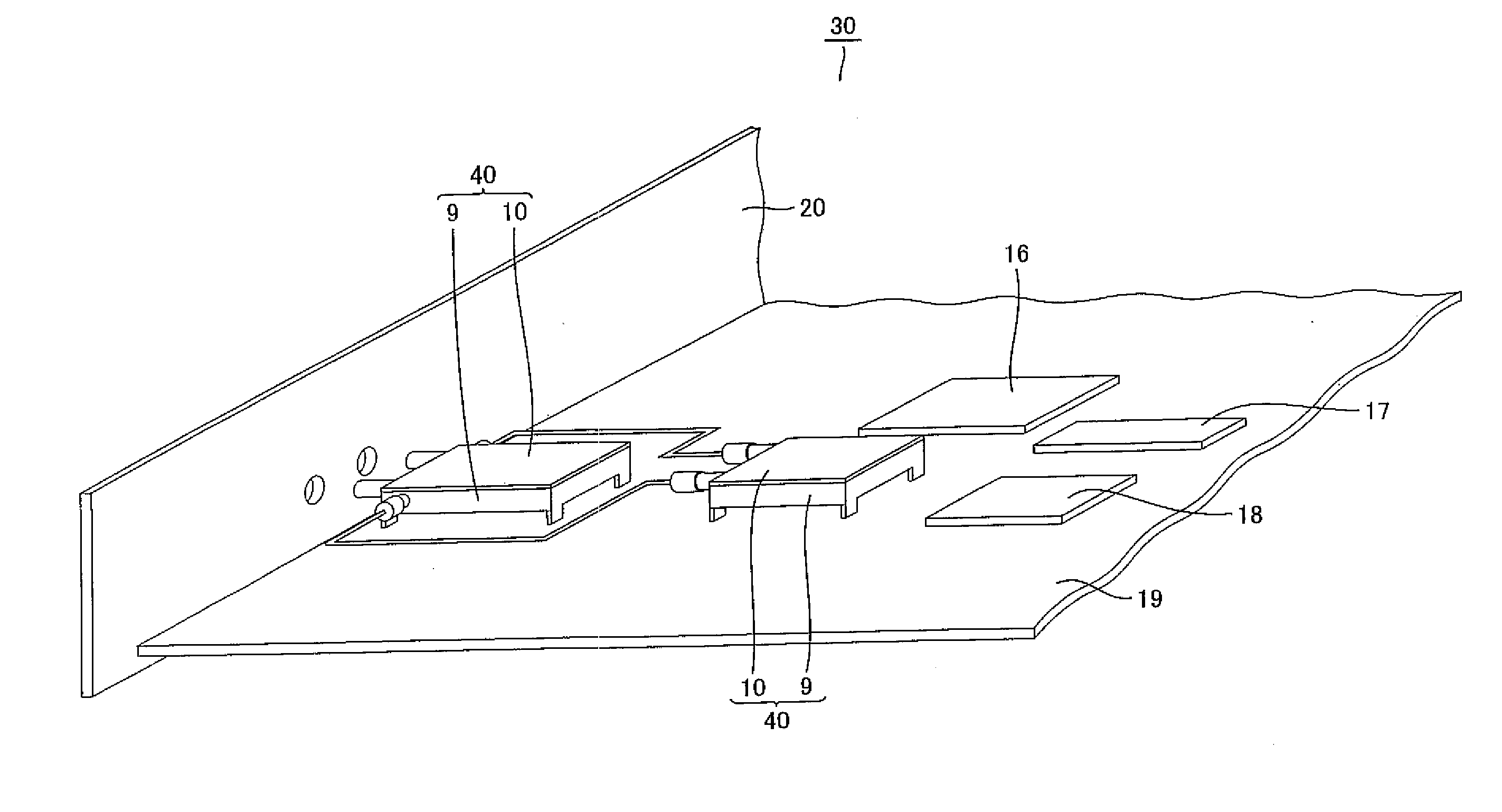
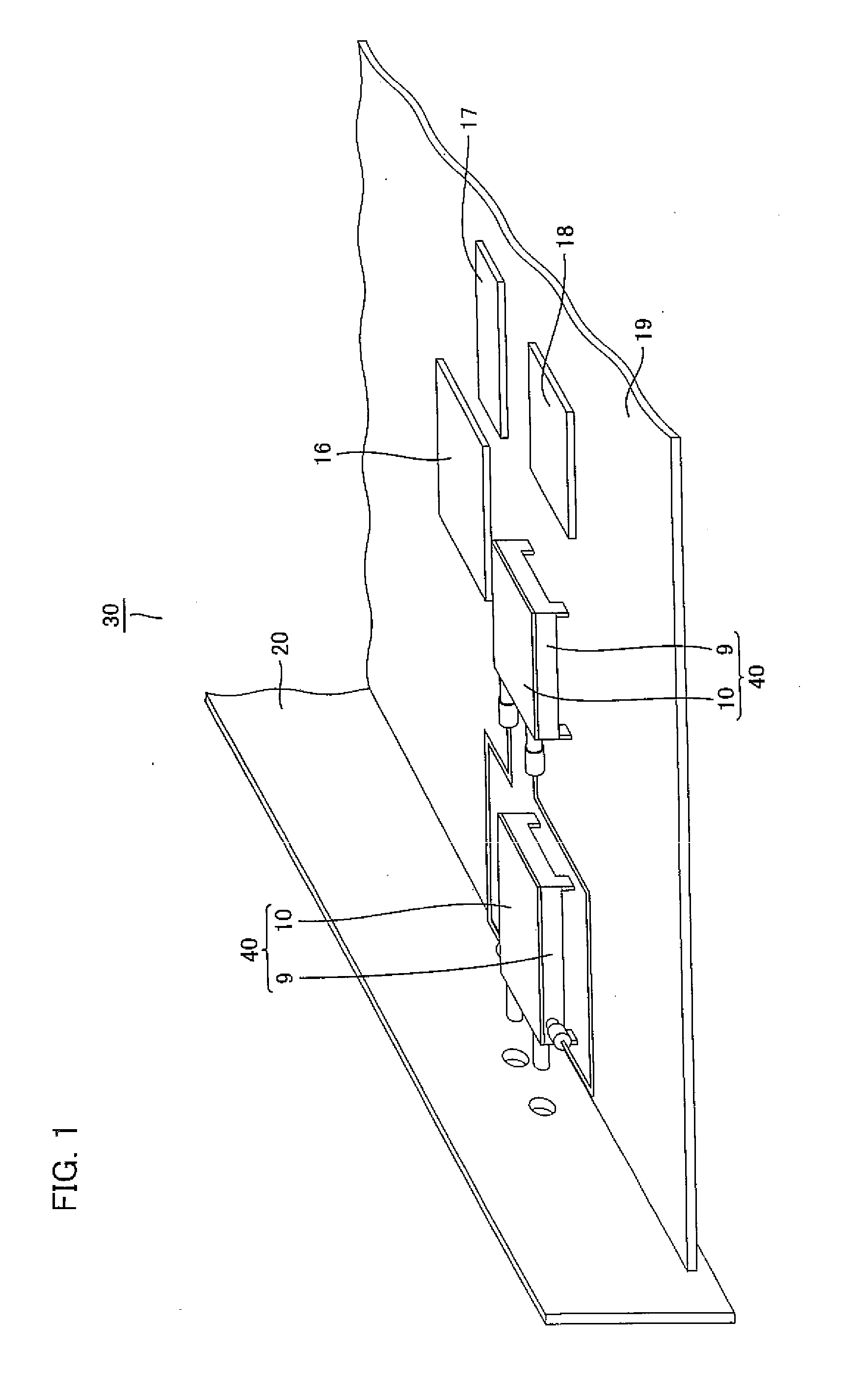
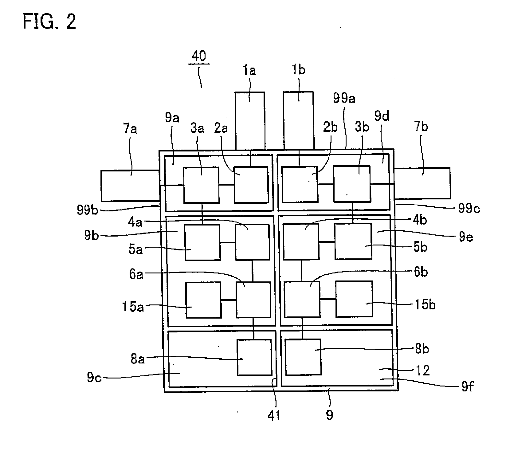
[0040]For high frequency receiver main body 40 of tuner 30 described above, the description has been given of an exemplary case where output connector 7a outputting the distributed RF signal for terrestrial broadcast and output connector 7b outputting the distributed RF signal for satellite broadcast are attached to the second side surface 99b and the third side surface 99c of shield case 9 facing each other, respectively. In addition, as shown in FIG. 3, output connectors 7a and 7b may be attached to shield lid 10, for example. Also in this case, interference between the RF signal for terrestrial broadcast and the RF signal for satellite broadcast can be suppressed.

second modification

[0041

[0042]It is desirable to employ a jack 21 and a plug 25 as output connector 7a or 7b (see FIG. 3). As an example of such a jack and a plug, as shown in FIG. 4, an F-type jack 22 and an F-type plug 26 excellent in high frequency characteristic may be employed, for example. In this case, a center contact 26a of F-type plug 26 is connected to a center contact 22a of F-type jack 22.

[0043]Further, as shown in FIG. 5, an RCA (Radio Cooperation of America) pin jack 23 and an RCA pin plug 27 widely used in terrestrial broadcast equipment may be employed, for example. In this case, a center contact 27a of RCA pin plug 27 is connected to a center contact 23a of RCA pin jack 23.

[0044]Furthermore, as shown in FIG. 6, an SMB (Sub Miniature Type B) jack 24 and an SMB plug 28 used in GHz band communication equipment may be employed, for example. In this case, a center contact 28a of SMB plug 28 is connected to a center contact 24a of SMB jack 24.

[0045]By employing a jack and a plug that are coax


PUM


Abstract

In a high frequency receiver main body 40, on a circuit board 12 within a shield case 9 with a bottom, distributors 3a and 3b, and filter circuits 4a and 4b, AGC amplification circuits 5a and 5b, mixers 6a and 6b, local oscillation circuits 8a and 8b, and demodulation circuits 15a and 15b for processing RF signals are provided. The inside of the shield case 9 is partitioned by a partition member 41 into six regions, and sealed with a shield lid. Input connectors 1a and 1b are attached to a first side surface of the shield case 9. An output connector 7a outputting an RF signal distributed by the distributor 3a is attached to a second side surface thereof. An output connector 7b outputting an RF signal distributed by the distributor 3b is attached to a third side surface thereof.

Description


Claims


Application Information

Patent Timeline
Owner SHARP KK
Why Eureka
Try Eureka