Wirelessly controlled light emitting display system

a display system and light-emitting display technology, applied in the direction of identification means, lighting support devices, instruments, etc., can solve the problems of difficult repair and/or replacement of individual components, heavy and bulky display systems, etc., and achieve easy repair and/or replacement of individual assemblies, reduce thickness, and reduce the effect of profil

Inactive Publication Date: 2009-01-08
TE CONNECTIVITY CORP
View PDF8 Cites 31 Cited by
  • Summary
  • Abstract
  • Description
  • Claims
  • Application Information

AI Technical Summary

Benefits of technology

The technical effect of this patented technology relates to making it easier and more efficient to install wireless control lights on small spaces while also allowing them to be easily installed without requiring complex equipment such as cables. Additionally, there can be flexibility with regards how different colors may appear when they're displayed by each unit individually.

Problems solved by technology

This patented technical problem addressed by this patents relates to improving the design of smaller and lighter lights while maintaining their functionality over longer periods without requiring frequent replacements or maintenance.

Method used


Image

  • Wirelessly controlled light emitting display system
  • Wirelessly controlled light emitting display system
  • Wirelessly controlled light emitting display system

Examples


Embodiment Construction

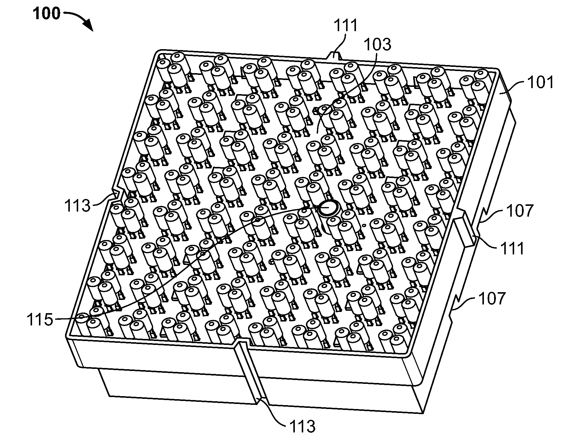
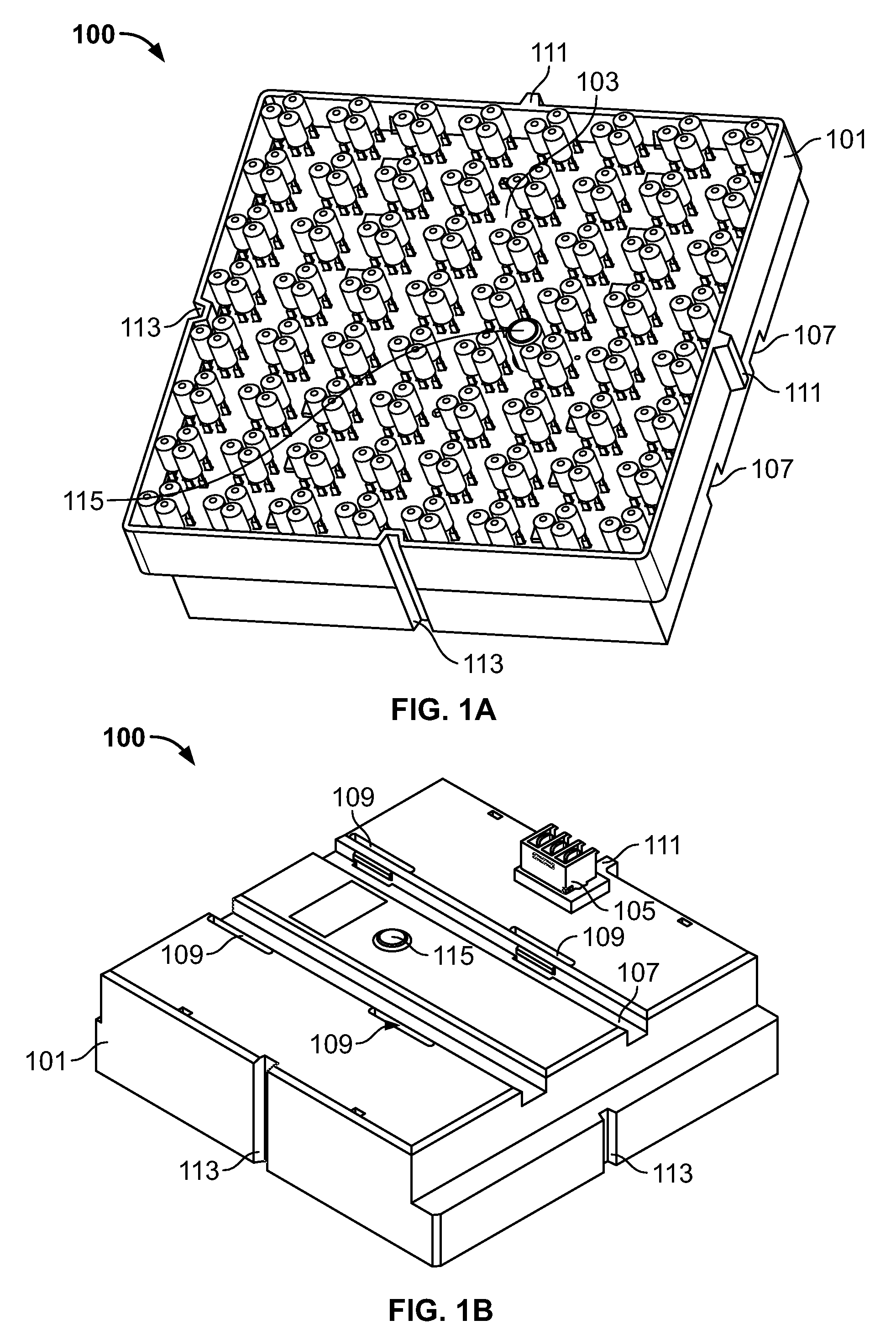
[0023]FIG. 1A and 1B show a light emitting assembly 100 according to an embodiment of the present invention. The light emitting assembly 100 includes a housing 101 having a light emitting device 103 (see FIG. 1A) engaged therewith. The light emitting device 103 is preferably detachably engaged with the housing 101, but may be affixed via adhesive or other method, if desired. In addition, the light emitting device 103 may be sealed into a housing with a potting compound or similar material. The light emitting device 103 may be any light emitting device 103 capable of wireless control. “Wireless control”, “wireless operation” and grammatical variations thereof includes programming, operating, controlling, activating, deactivating or any other functions imparted upon the light emitting device 103 in response to a wireless signal, in real time, delayed or from storage, capable of transmitting information or operational instructions, such as, but not limited to, a radio frequency signal. Fo


PUM


Abstract

A light emitting assembly, and wirelessly controlled light emitting assembly for use in a lighted display having a housing body configured to receive a light emitting device having a plurality of wirelessly controlled light emitting elements. The housing body includes at least one mounting feature arranged and disposed to maintain a relative positioning of the light emitting assembly with respect to another light emitting assembly.

Description


Claims


Application Information

Patent Timeline
Owner TE CONNECTIVITY CORP
Why Eureka
Try Eureka