Turbine Vane Securing Mechanism

a technology of securing mechanism and turbine vane, which is applied in the direction of machines/engines, liquid fuel engines, other chemical processes, etc., can solve the problems of reducing the useful life of the turbine vane and causing wear

Inactive Publication Date: 2009-02-26
SIEMENS ENERGY INC
View PDF16 Cites 10 Cited by
  • Summary
  • Abstract
  • Description
  • Claims
  • Application Information

AI Technical Summary

Benefits of technology

This patented technology describes how it can help reduce vibrations caused by moving parts within gas turbines when they operate correctly. It involves attaching a special part called a mount on top of one or more components like blades used for power generation. These brackets have teeth at their ends where bolts attach them together securely. When these bolts get tightened enough, there's no longer any space left around those roots inside which other things could cause damage.

Problems solved by technology

This patented technical problem addressed by this patents relates to reducing damage caused during engine operation due to excess heat generated when certain components inside these types of machines experience higher temperature than usual. Existing solutions involve adding extra parts like cooled pipings around the ends of the fan's vanes, but they can also cause issues related to vibration and reduced lifetimes over time.

Method used


Image

  • Turbine Vane Securing Mechanism
  • Turbine Vane Securing Mechanism
  • Turbine Vane Securing Mechanism

Examples


Embodiment Construction

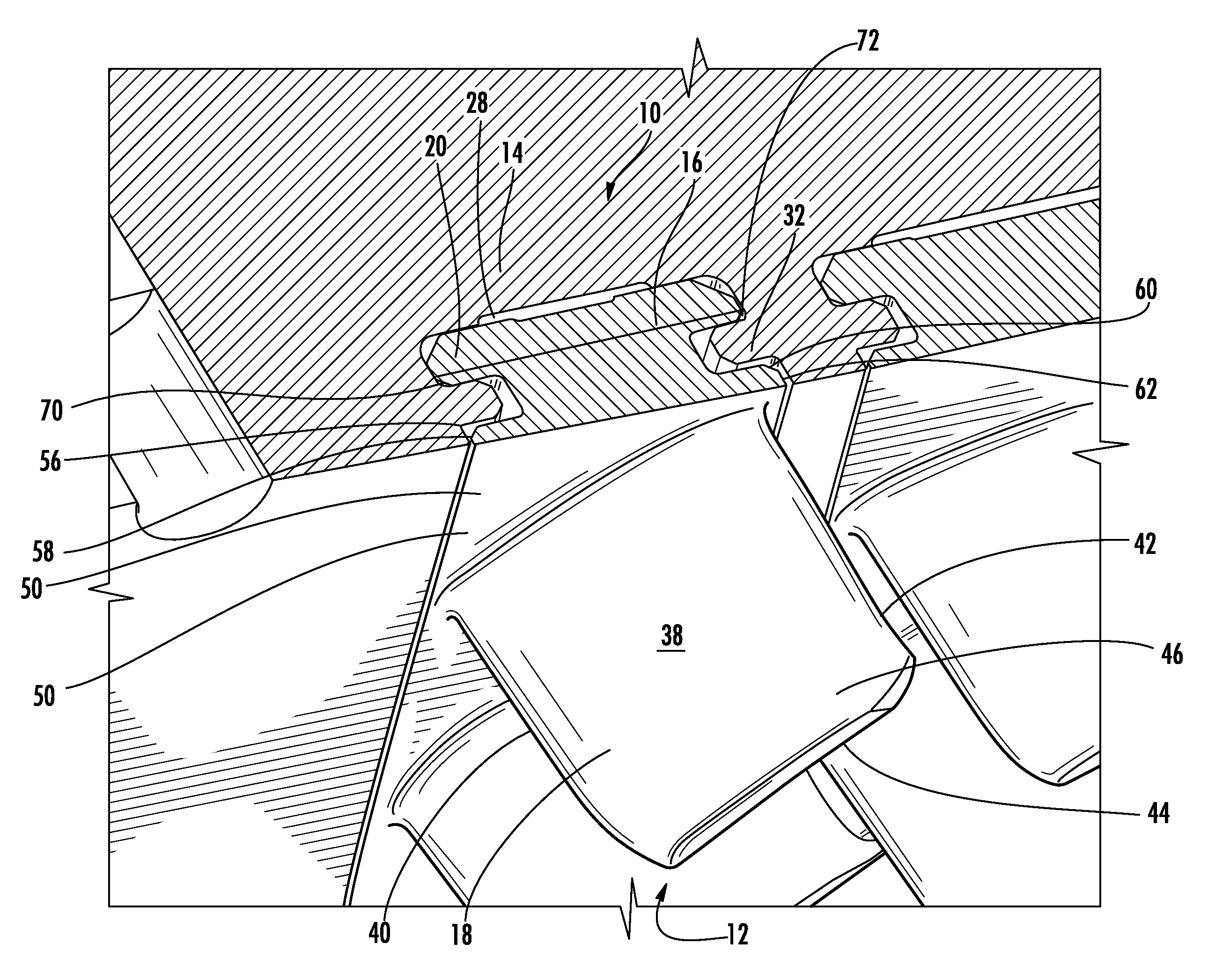
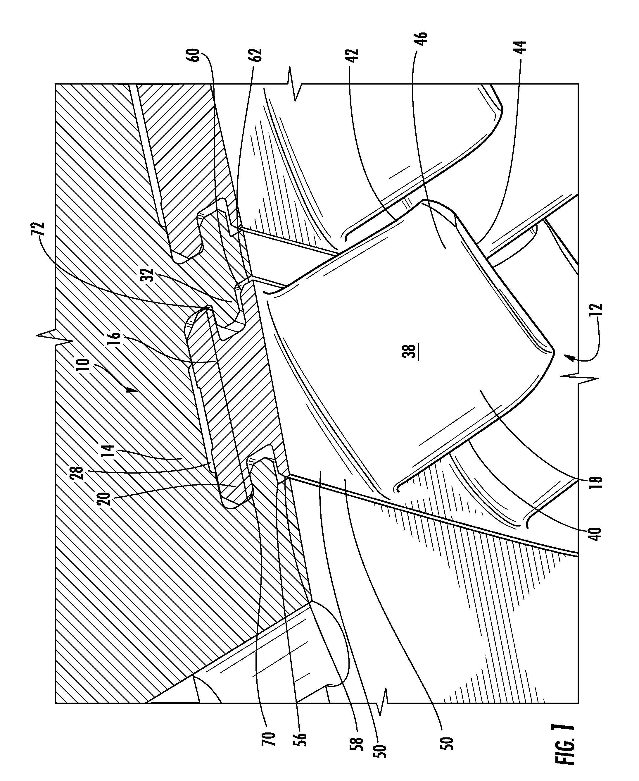
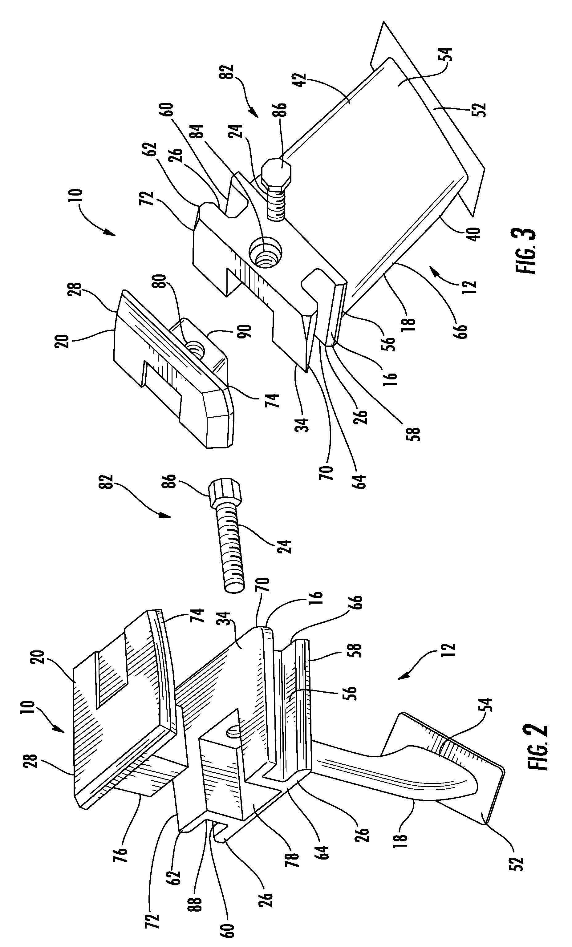
[0019]As shown in FIGS. 1-8, this invention is directed to a turbine vane attachment system 10 configured to eliminate movement of a turbine vane 12 relative to a turbine vane carrier 14 during turbine engine operation. The turbine vane attachment system 10 is usable with turbine vanes 12 in the turbine and compressor sections of a turbine engine. The turbine vane attachment system 10 may include a base 16 attached to a turbine airfoil 18. The base 16 may be configured to contact a wedge support 20 along a plane 22 that is generally nonparallel and nonorthogonal with a longitudinal axis 23 of the airfoil 18. A connection system 82, such as, but not limited to, a bolt 24 may connect the base 16 with the wedge support 20. As the bolt 24 is advanced, a distance between a channel 26 in the base 16 and an outer bearing surface 28 increases. The turbine vane 12 may be positioned in a vane carrier 30 such that tongues 32 extending from the vane carrier 30 are positioned in the channels 26. As


PUM


Abstract

A turbine vane attachment system configured to eliminate movement of a turbine vane relative to a turbine vane carrier. The turbine vane attachment system may include a base attached to a turbine airfoil. The base may be configured to contact a wedge support along a plane that is generally nonparallel and nonorthogonal with a longitudinal axis of the airfoil. A bolt may connect the base with the wedge support. The bolt may change a distance between a channel in the base and an outer bearing surface. The turbine vane may be positioned in a vane carrier such that tongues extending from the vane carrier are positioned in the channels. As the bolt is advanced, the wedge support is moved laterally along the support surface of the base and the channels engage the tongues, thereby preventing movement of the turbine vane.

Description


Claims


Application Information

Patent Timeline
Owner SIEMENS ENERGY INC
Why Eureka
Try Eureka