Steering assembly

Active Publication Date: 2009-05-21
HYUNDAI MOBIS CO LTD +1
View PDF23 Cites 6 Cited by
  • Summary
  • Abstract
  • Description
  • Claims
  • Application Information

AI Technical Summary

Benefits of technology

[0008]In the steering assembly according to the present invention, connection parts formed in the mounting plate body can be directly fixed to the steering w

Problems solved by technology

For this reason, there are problems in that it is inconvenient to

Method used


Image

  • Steering assembly
  • Steering assembly
  • Steering assembly

Examples


Embodiment Construction

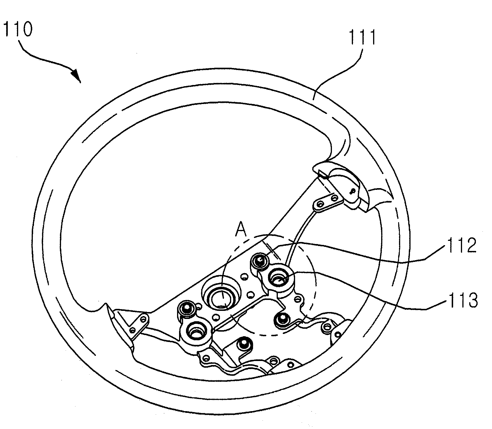
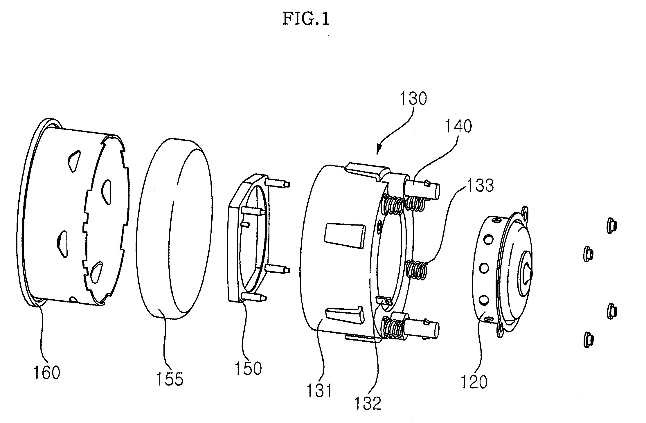
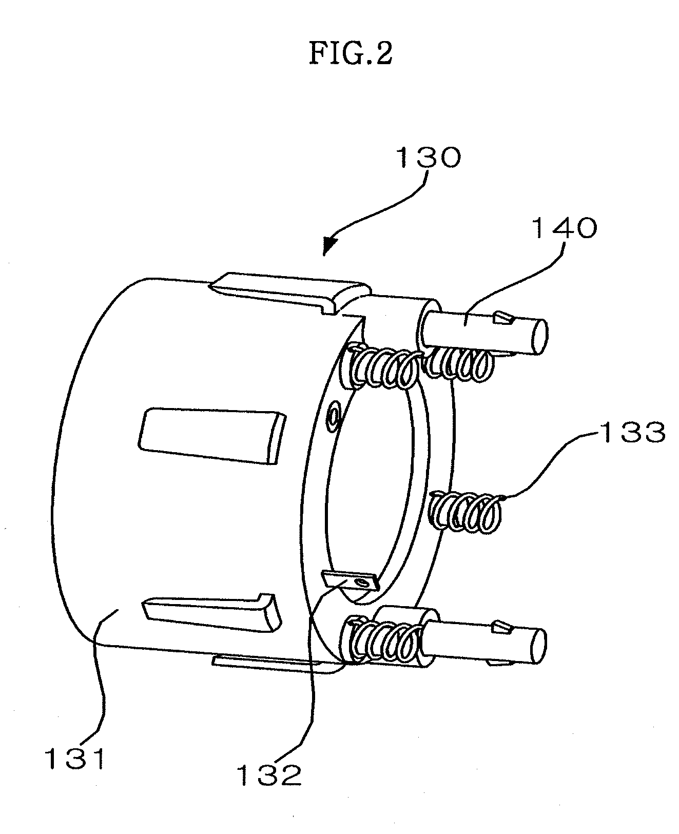
[0019]FIG. 1 is an exploded perspective view of a steering assembly 100 according to an embodiment the present invention. FIG. 2 is a perspective view of a mounting plate assembly 130 shown in FIG. 1. FIG. 3 is a perspective view of a steering wheel module 110 shown in FIG. 1. FIG. 4 is a cross-sectional view of an example of a connection part 140 shown in FIG. 2. FIG. 5 is a cross-sectional view showing that the mounting plate assembly 130 shown in FIG. 2 and the steering wheel module 110 shown in FIG. 3 are assembled to each other.

[0020]Referring to FIG. 1, the steering assembly 100 includes a steering wheel module 110, an inflator 120, a mounting plate assembly 130, a retainer ring assembly 150, a cushion 155, and a cover 160. The steering wheel module controls the direction of a vehicle. The inflator is provided on the steering wheel module 110, and discharges compressed air. The mounting plate assembly is fitted to the inflator 120 and the steering wheel module 110, and serves as


PUM


Abstract

A steering assembly according to the present invention includes connection parts that are formed in a mounting plate body and fixed to a steering wheel module. Accordingly, when the mounting plate assembly is fixed to a steering wheel module, it is possible to attach or detach the mounting plate assembly to or from the steering wheel module. As a result, it is possible to quickly assemble the mounting plate assembly and the steering wheel module.

Description


Claims


Application Information

Patent Timeline
Owner HYUNDAI MOBIS CO LTD
Why Eureka
Try Eureka