Temperature compensation method for laser power of an optical disk drive

Inactive Publication Date: 2009-05-28
QUANTA STORAGE INC
View PDF3 Cites 1 Cited by
  • Summary
  • Abstract
  • Description
  • Claims
  • Application Information

AI Technical Summary

Benefits of technology

[0009]According to a first aspect of the present invention, a temperature compensation method for laser power of an optical disk drive is provided. The laser power is compensated in two phases to improve the correctness in the output of laser power by obtaining two-phase linear-fitting power curves from laser power curves of different temperatures by use of a laser power turning point.
[0010]To achieve the above objects of the invention, a temperature compensation method for laser power of an optical disk drive is provided. A predetermined linear-fitting power curve and a temperature-changing slope curve of the predetermined linear-fitting power curve are previously stored in an optical d

Problems solved by technology

Laser diode is very sensitive to temperature, and temperature change will change the wavelength of the light emitted by laser diode and make the laser power difficult to maintain stable, hence affecting the quality of reading/writing data by the optical disk drive.
As the temperature of the optical disk drive rises when the optical disc drive operates, the laser power is too high or the working environment is h

Method used


Image

  • Temperature compensation method for laser power of an optical disk drive
  • Temperature compensation method for laser power of an optical disk drive
  • Temperature compensation method for laser power of an optical disk drive

Examples


Embodiment Construction

[0018]The technologies and methods used to achieve the above objects of the invention are exemplified in the following preferred embodiments with accompanying drawings.

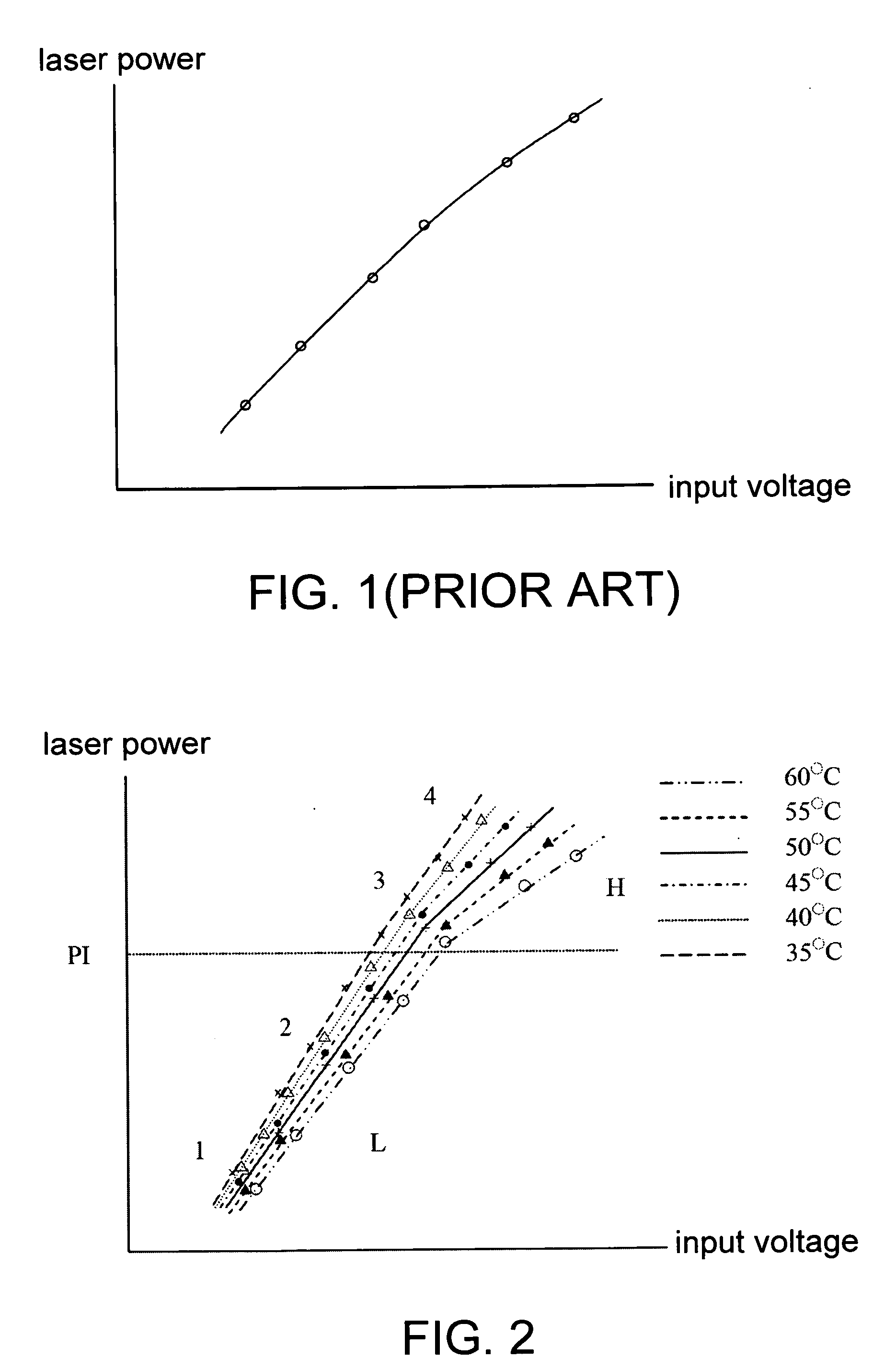
[0019]Referring to FIG. 2, a linear-fitting power curve of a temperature compensation method for laser power according to a preferred embodiment of the invention is shown. The invention obtains the optical disk drive linear-fitting power curve by use of practical measuring and curve fitting. Firstly, an optical disc drive is tested at different temperatures. In the present embodiment of the invention, the temperatures 35° C., 40° C., 45° C., 50° C., 55° C., and 60° C. are used as examples. When the optical disk drive is controlled to operate at a particular temperature and a plurality of different voltages (or currents) are respectively inputted to the laser diode, an output of laser power corresponding to each input voltage is detected and the testing result is recorded, and several test points are formed on the coordin


PUM


Abstract

A temperature compensation method for laser power in an optical disk drive is provided. A predetermined linear-fitting power curve and a temperature-changing slope curve are previously stored in the optical disk drive. Firstly, an output of laser power is controlled according to the predetermined linear-fitting power curve to read/write data. Next, the temperature of the disk drive is detected. Then, whether the temperature has changed is checked. If the temperature has not changed, the method continues to read/write data. If the temperature has changed, the method obtains a relative slope from the slope curve by use of the temperature of the disk drive, displaces the slope of the predetermined linear-fitting power curve with the obtained relative slope to form a new linear-fitting power curve for replacing the predetermined linear-fitting power curve, and controls the output of laser power.

Description


Claims


Application Information

Patent Timeline
Owner QUANTA STORAGE INC
Why Eureka
Try Eureka