Method and apparatus of building ip-based video service system in hybrid fiber coax network

Inactive Publication Date: 2009-06-18
ELECTRONICS & TELECOMM RES INST
View PDF6 Cites 1 Cited by
  • Summary
  • Abstract
  • Description
  • Claims
  • Application Information

AI Technical Summary

Benefits of technology

[0011]Another aspect of the present invention also provides a method of eliminating an IP-encapsulated portion in a headend, transmitting a video signal to a subscriber apparatus, and per

Problems solved by technology

Overhead caused by the IP encapsulation when transmitting an IP-based video to a Data Over Cable Service Interface Specifications (DOCSIS) channel may waste scarce resources of the HFC network using the ubiquitous IP protocol and an address system in order to support various viewing forms of users and to provide a multicast service of only a request program.
A DOCSIS protocol supports

Method used


Image

  • Method and apparatus of building ip-based video service system in hybrid fiber coax network
  • Method and apparatus of building ip-based video service system in hybrid fiber coax network
  • Method and apparatus of building ip-based video service system in hybrid fiber coax network

Examples


Embodiment Construction

[0019]Reference will now be made in detail to exemplary embodiments of the present invention, examples of which are illustrated in the accompanying drawings, wherein like reference numerals refer to the like elements throughout. The exemplary embodiments are described below in order to explain the present invention by referring to the figures.

[0020]When detailed descriptions related to a well-known related function or configuration are determined to make the spirits of the present invention ambiguous, the detailed descriptions will be omitted herein. Also, terms used throughout the present specification are used to appropriately describe exemplary embodiments of the present invention, and thus may be different depending upon a user and an operator's intention, or practices of application fields of the present invention. Therefore, the terms must be defined based on descriptions made through the present invention.

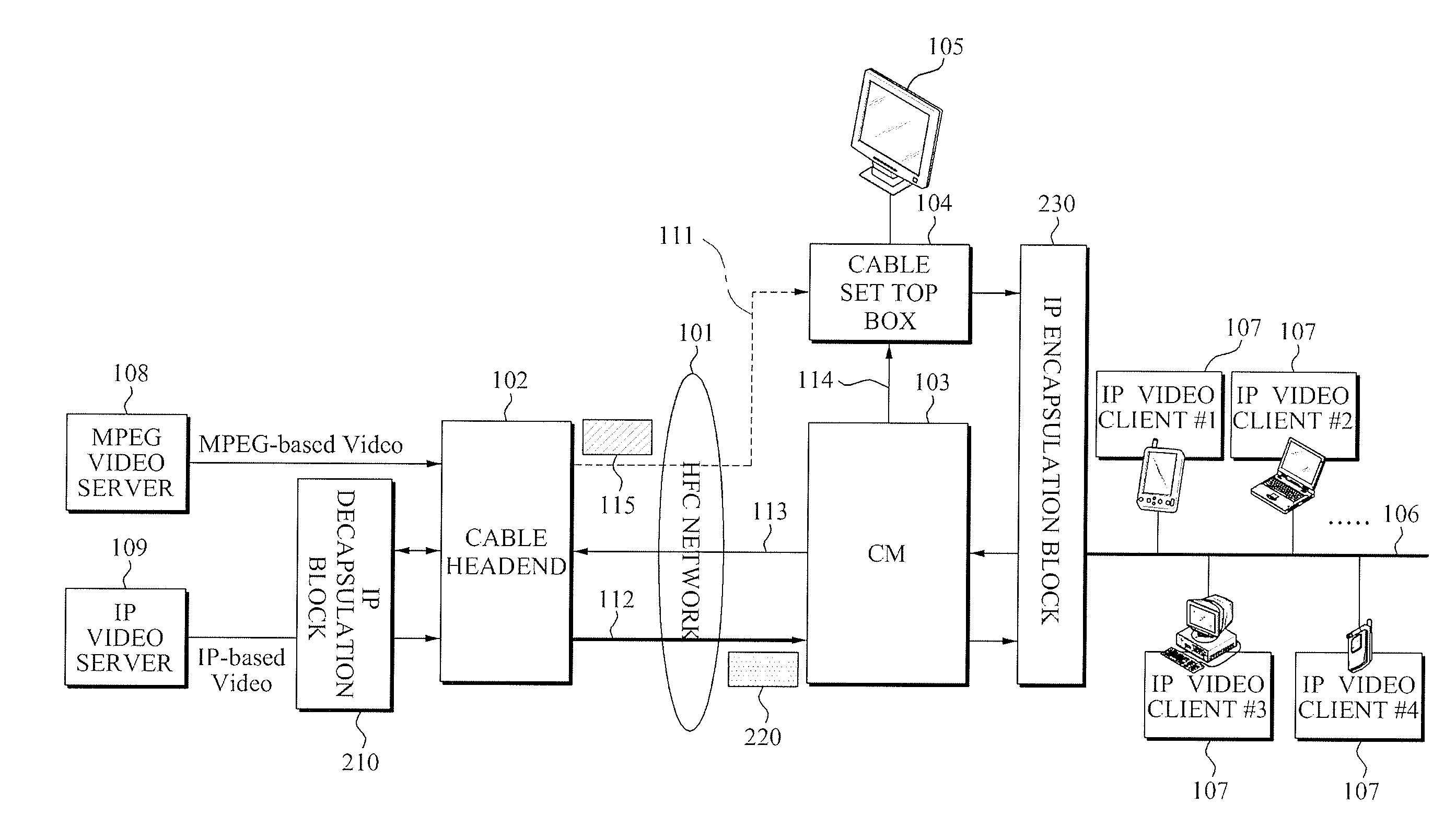
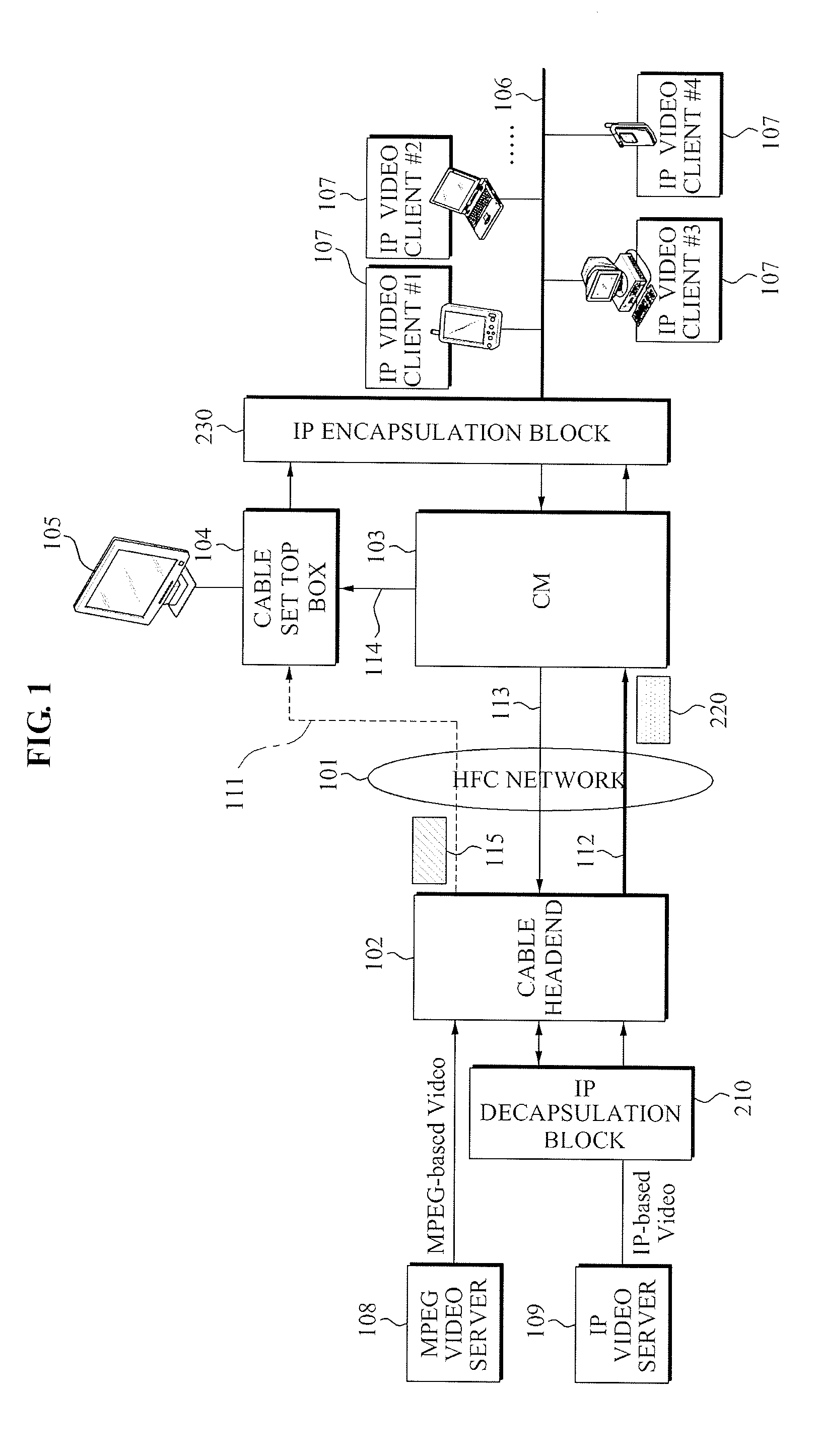
[0021]Since a form of a legacy broadcasting service changes from a broadca


PUM


Abstract

An apparatus and method of building an Internet Protocol (IP)-based video service system in a Hybrid Fiber Coax (HFC) network is provided. An apparatus for building an IP-based video service providing system, the apparatus including: an IP decapsulation unit to delete a header in a video signal in a packet form transmitted by an IP-based video server, and to subsequently transmit the video signal to a headend; the headend to encapsulate the video signal received by the IP decapsulation unit into a Media Access Control (MAC) header, and to transmit the encapsulated video signal in the packet form; and an IP protocol encapsulation unit to perform IP encapsulation of the video signal received from the headend.

Description


Claims


Application Information

Patent Timeline
Owner ELECTRONICS & TELECOMM RES INST
Why Eureka
Try Eureka