Apparatus for sensing a mount for optical lenses and associated method

a technology of optical lenses and mounts, applied in the field of apparatus for sensing mounts for optical lenses, can solve the problems of inaccurate measurement of mount dimensions, difficulty in assembling lenses, and apparatus of the above-mentioned typ

Active Publication Date: 2009-07-09
LUNEAU TECH OPERATIONS
View PDF10 Cites 14 Cited by
  • Summary
  • Abstract
  • Description
  • Claims
  • Application Information

AI Technical Summary

Benefits of technology

The present invention relates to an apparatus used to sense the orientation of a device on a surface. This sensor has two parts: one part controls how far it moves when the device is mounted onto another object or adjusts its direction of movement based on the angle at which it's attached to the other object.

Problems solved by technology

This patent describes a problem where sensors used to detect the shape of a mount cannot accurately determine their position in relation to other components such as the mount itself. Specifically, if there were elongation and/or angular variations in the mount's location caused by changes in the mount's orientation, errors can occur during grinding.

Method used


Image

  • Apparatus for sensing a mount for optical lenses and associated method
  • Apparatus for sensing a mount for optical lenses and associated method
  • Apparatus for sensing a mount for optical lenses and associated method

Examples


Embodiment Construction

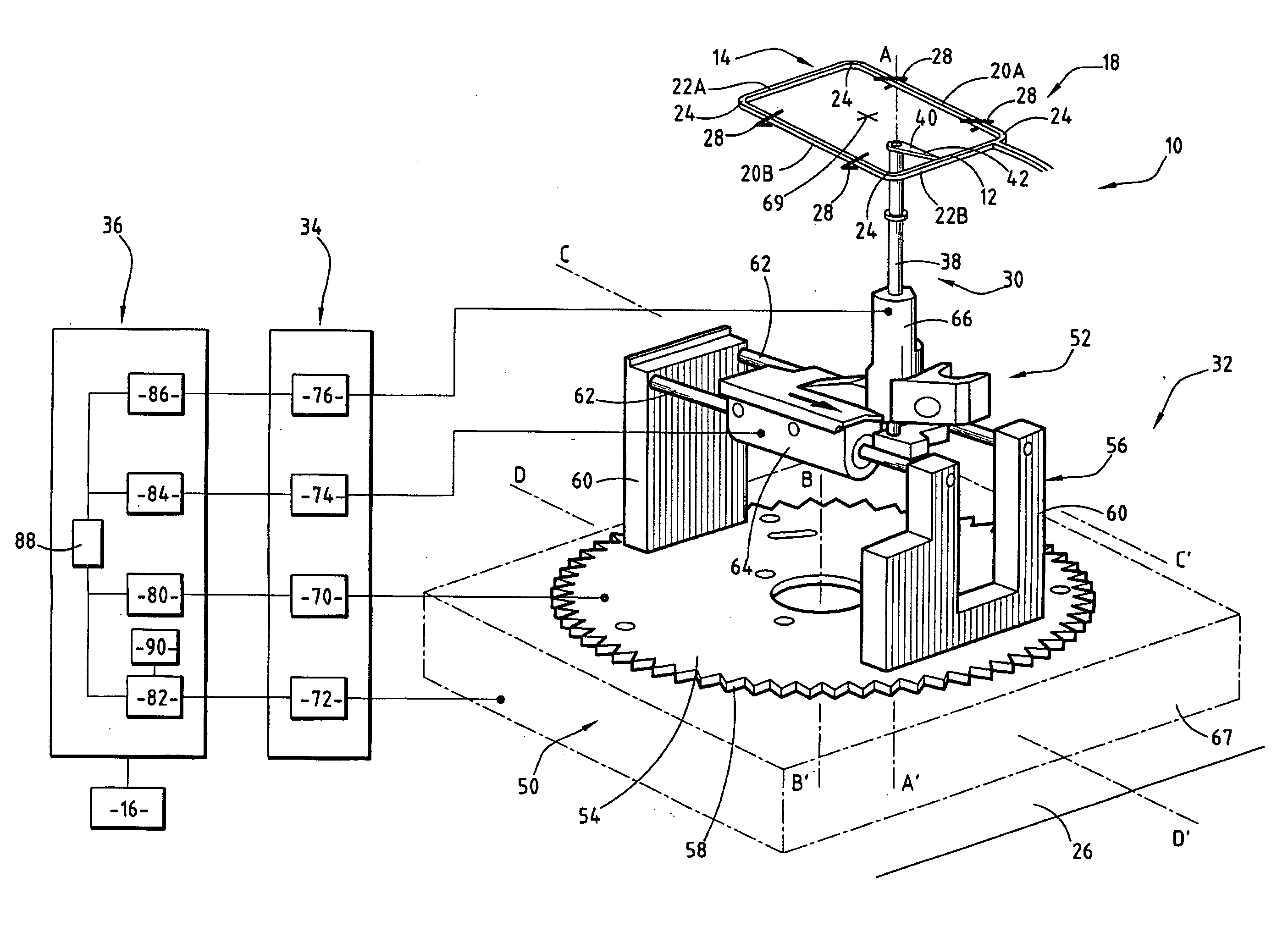
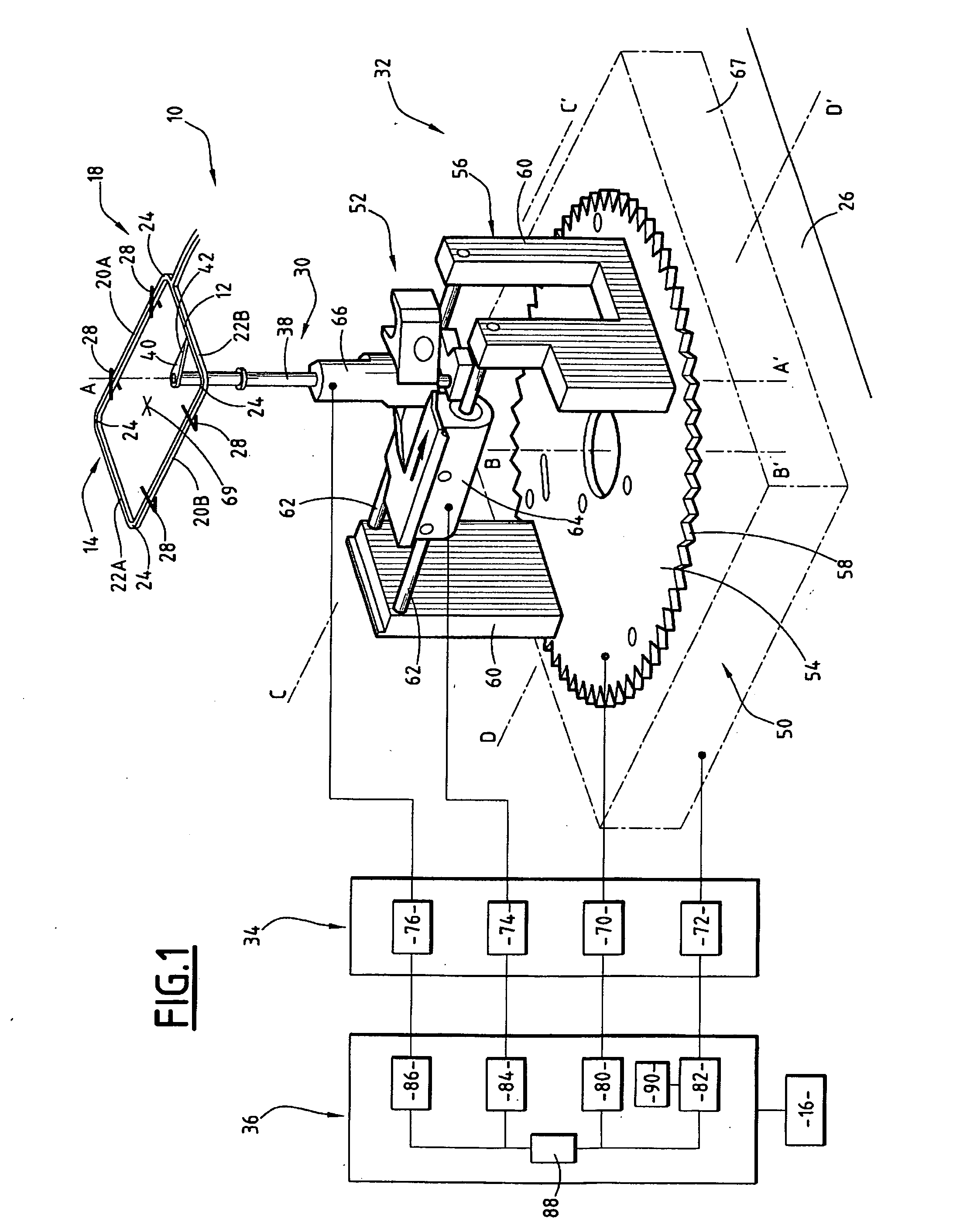
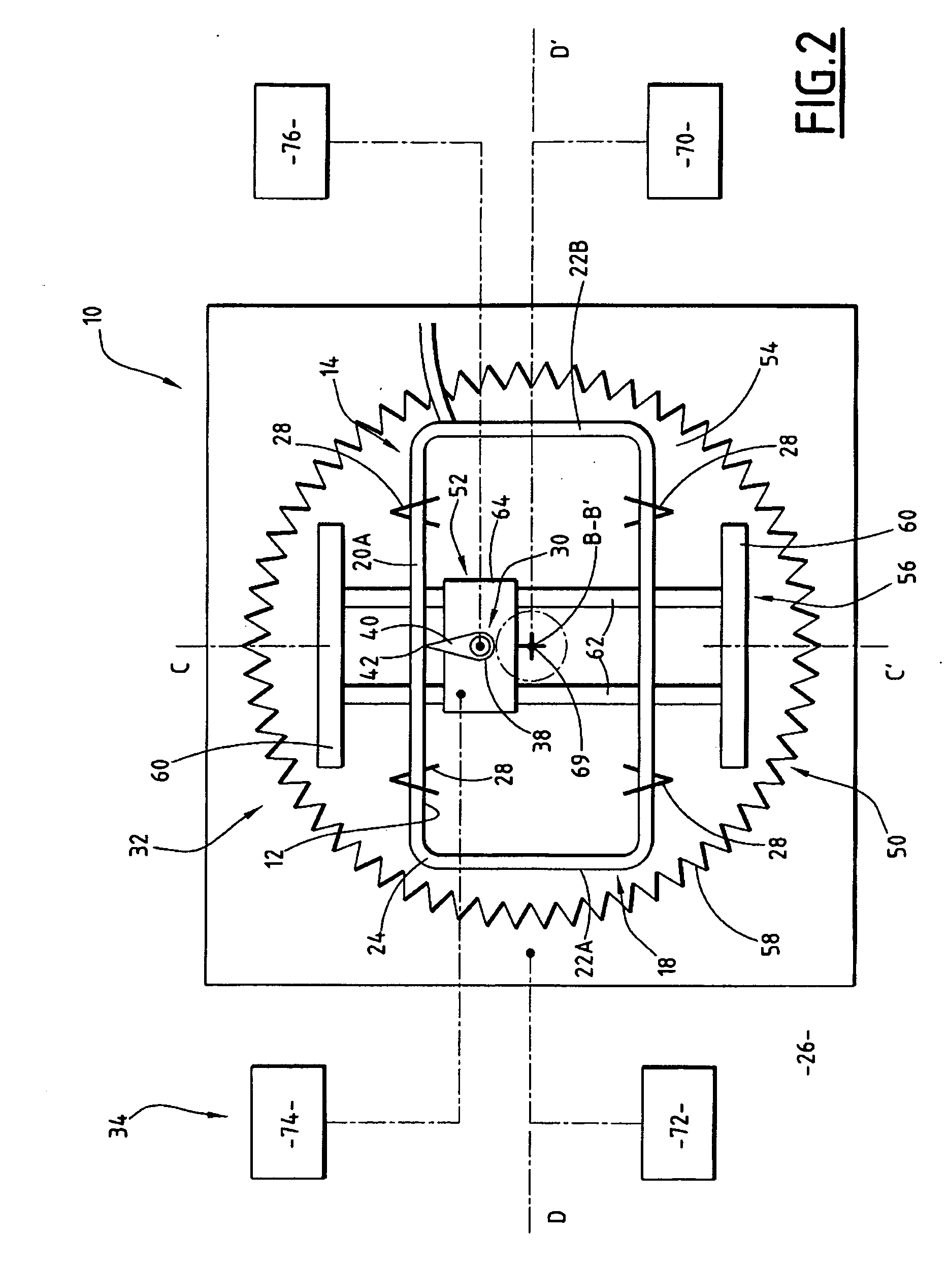
[0043]A first sensing apparatus 10 according to the invention is shown in FIGS. 1 to 3.

[0044]The apparatus 10 is intended to measure the exact profile of a groove 12 defined in a mount 14 for optical lenses, shown partially in FIGS. 1 to 3. The sensing apparatus 10 is arranged in a machine 16 for grinding optical lenses, for example of the type described in application FR-A-2 852 878 by the Applicant.

[0045]As illustrated in FIGS. 1 and 2, the mount 14 comprises two mount rims 18, only one of which is visible in these Figures. Each mount rim 18 defines internally a groove 12.

[0046]Each mount rim 18 has a substantially horizontal mean directrix surface in FIG. 1. Each rim 18, in projection in a horizontal plane, has an elongate and angular contour. Thus, it comprises two sections, upper 20A and lower 20B, connected to each other by two lateral sections 22A, 22B having a length which is shorter by a factor of at least two. Each rim 18 comprises between each section 20A, 20B and an adjacen


PUM


Abstract

The apparatus (10) comprises a turret (50), rotatable about a first axis (B-B′), a slide (52) mounted on the turret (50) and a sensor (30) mounted for sliding in the slide (52) along a third axis (C-C′) substantially parallel to the first axis (B-B′).
It comprises means (34) for displacement of the sensor for displacing a contact surface (42) of the sensor along the mount (14) during the sensing of the mount. The displacement means (34) comprise means (70) for driving the turret (50) in rotation about the first axis (B-B′).
The apparatus comprises control means (82) for controlling means (72) for displacement of the turret in a plane perpendicular to the first axis (B-B′) and suitable for displacing the turret (50) in said plane when the turret is driven in rotation about the first axis (B-B′) during the sensing of the mount.

Description


Claims


Application Information

Patent Timeline
Owner LUNEAU TECH OPERATIONS
Why Eureka
Try Eureka