System for Monitoring Individual Photovoltaic Modules

Inactive Publication Date: 2009-07-16
MOULTON THOMAS A +1
View PDF7 Cites 149 Cited by
  • Summary
  • Abstract
  • Description
  • Claims
  • Application Information

AI Technical Summary

Benefits of technology

[0014]The system of the present invention essentially provides sensors to identify the sufficiency, output, efficiency and most other relevant conditions of components of a solar array, particularly individual PV modules. In the manner employed by the system, the present invention affords users the ability to know exactly which PV module is underperforming. In the preferred embodiment of the present invention, two pairs of wires are connected to the voltage level sensing circuit in a manner that a sensor is effective

Problems solved by technology

However, current solar array technology is not perfect as deference to the solar technology grows exponentially.
The primary issue with solar arrays relates to the PV modules that serve to make up a solar array.
PV modules typically experience individual detriments such as life span, poor connection, dirt buildup and individual degradation.
When a PV module experiences such a detriment, the efficiency of the entire solar array may be affect

Method used


Image

  • System for Monitoring Individual Photovoltaic Modules
  • System for Monitoring Individual Photovoltaic Modules
  • System for Monitoring Individual Photovoltaic Modules

Examples


Embodiment Construction

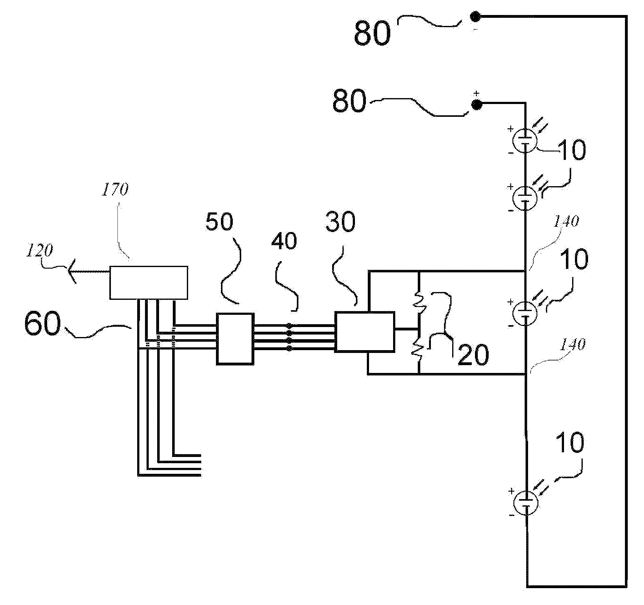
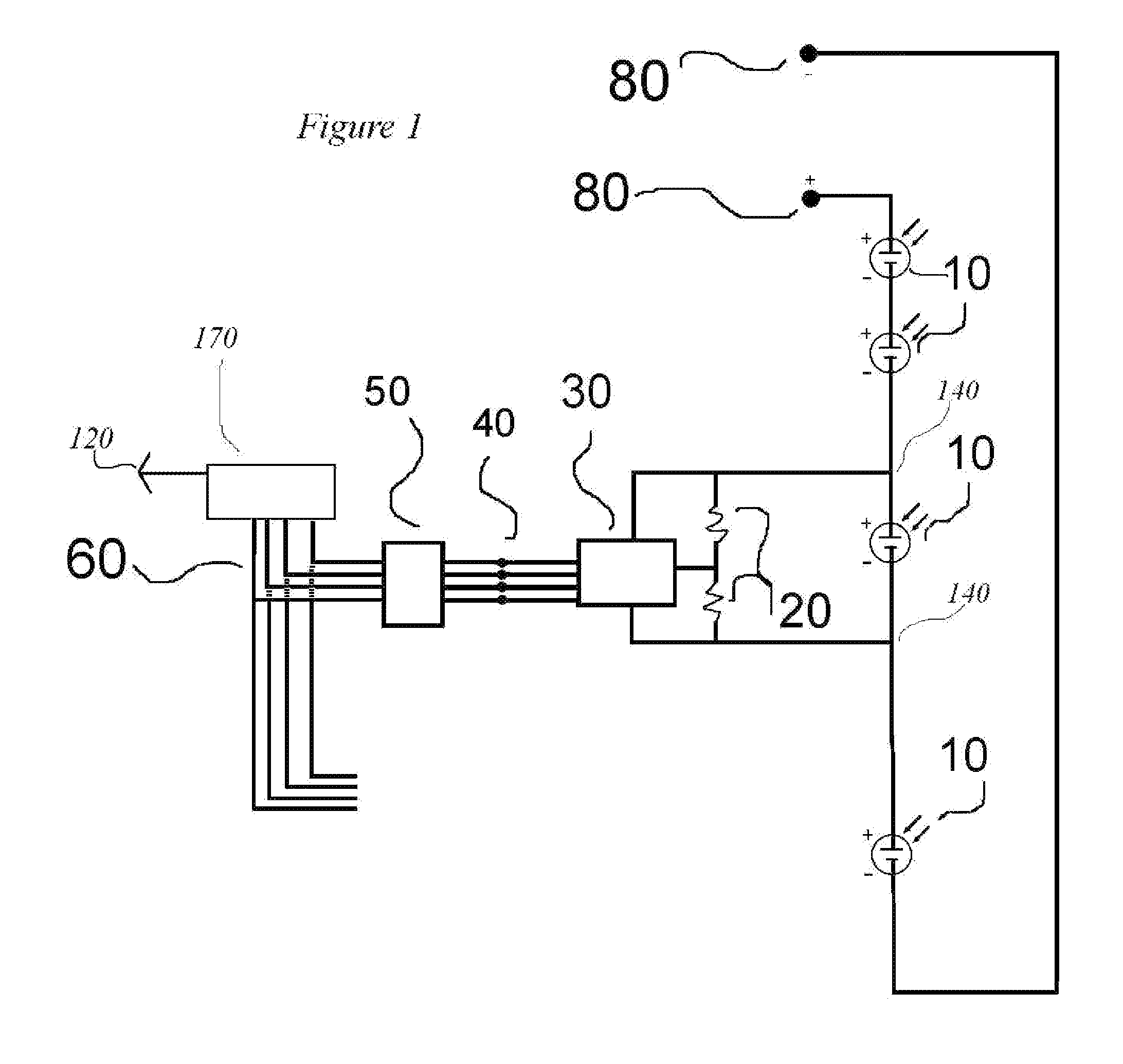
[0015]FIG. 1 is a schematic view of the present invention using a wired system

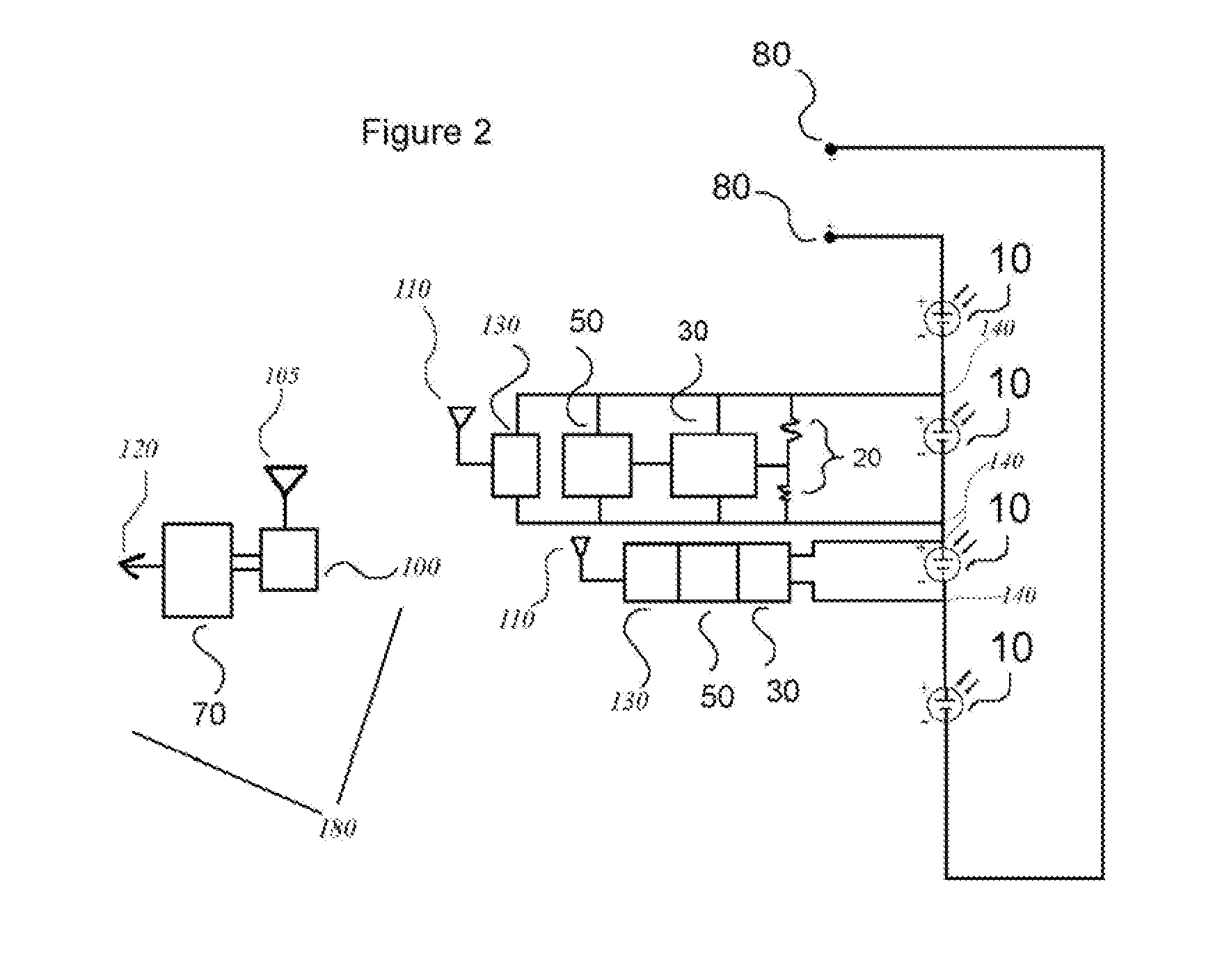
[0016]FIG. 2 is a schematic view of the present invention using a wireless system

[0017]FIG. 3 is a schematic view of the present invention using a signaling over power system

DETAILED DESCRIPTION OF THE PREFERRED EMBODIMENT

[0018]The system of the present invention uses sensing technology relating to individual PV modules (10) in order to detect fluctuations and relevant output levels of individual PV modules (10). FIG. 1 is a view of the present invention in its preferred embodiment. In this schematic view, we see how wired connections lead information directly from the individual PV modules (10) toward the system's sensing components of the overall solar array. The system receives power (140). A minimal amount of wires lead to the voltage level sensing circuit (20). The voltage level sensing circuit (20) receives voltage levels from the individual PV module (10) in its connection stream. In this manner, the


PUM


Abstract

A system for monitoring the power output levels for each photovoltaic module of a solar array. The system connects individual photovoltaic module with its own voltage level sensing circuit, where the power output data is transferred through wired and wireless means to be efficiently analyzed. In addition to isolating high voltage DC power for safer information, the system enables technicians to quickly ascertain the productivity levels, potential problems, solutions and exact locations relating to each specific photovoltaic module within a solar array.

Description


Claims


Application Information

Patent Timeline
Owner MOULTON THOMAS A
Why Eureka
Try Eureka