Load bearing stand

a technology for bearings and supports, applied in the direction of machine supports, domestic objects, applications, etc., can solve the problems of time-consuming and expensiv

Inactive Publication Date: 2009-08-27
BEASLEY DOUGLAS
View PDF7 Cites 5 Cited by
  • Summary
  • Abstract
  • Description
  • Claims
  • Application Information

AI Technical Summary

Benefits of technology

This patented technology allows multiple rod members that have different sizes or shapes can be used together with each other without being pulled away by gravity forces during use. These rod systems help prevent damage caused by external factors like vibrations or impacts on their components while still providing stability against tilting movements over time.

Problems solved by technology

The technical problem addressed in this patents relates to improving the construction process used on buried objects during drilling operations without causing damage from soil movement caused by factors like wind pressure or snow accumulation. Existing methods involve adding extra materials around the object being dug up beforehand making sure they stay secure when lifted off again after excavating material below certain levels. This can lead to increased costs associated with disposals and potential negative effects on surrounding areas.

Method used


Image

  • Load bearing stand
  • Load bearing stand
  • Load bearing stand

Examples


Embodiment Construction

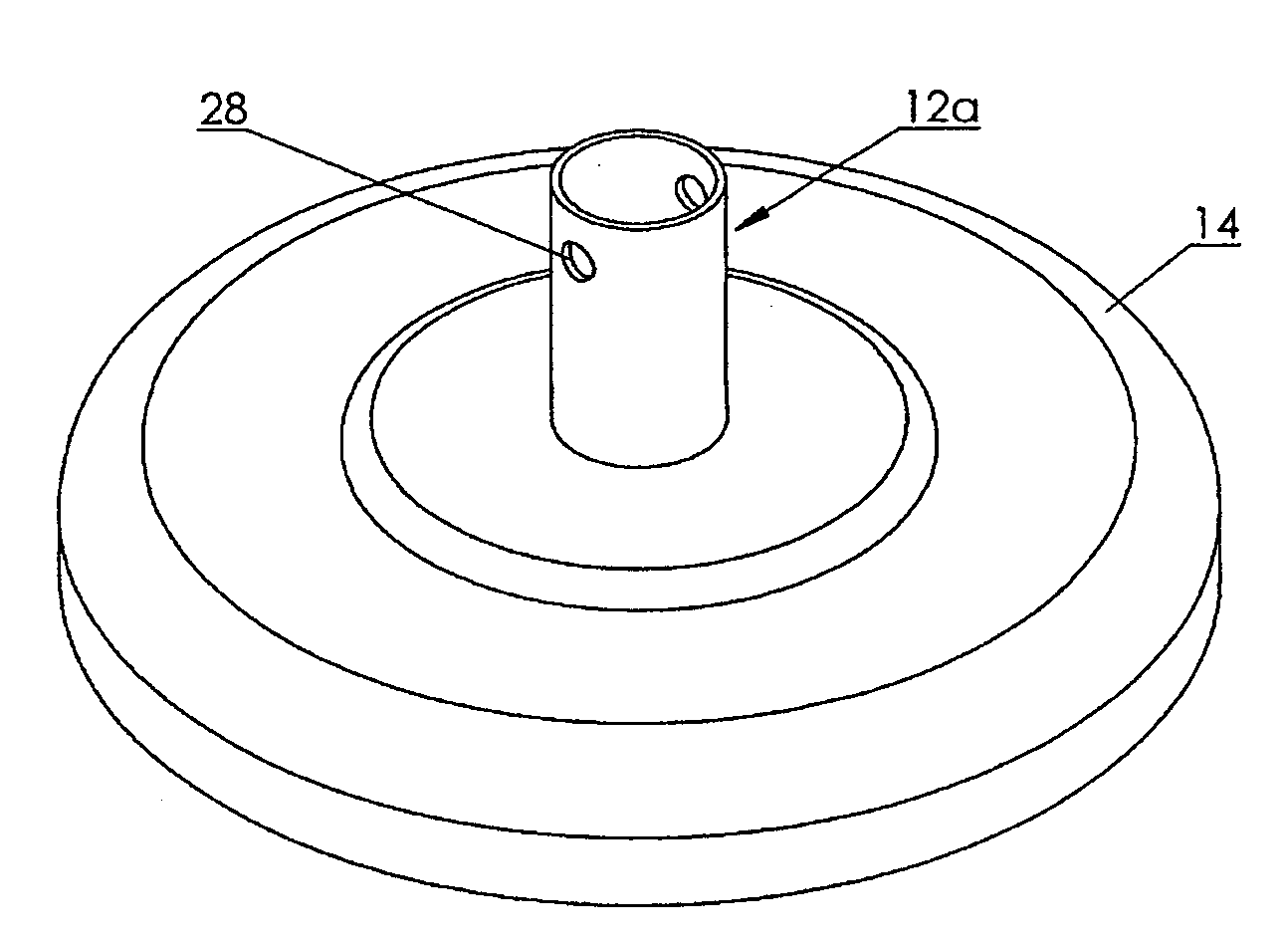
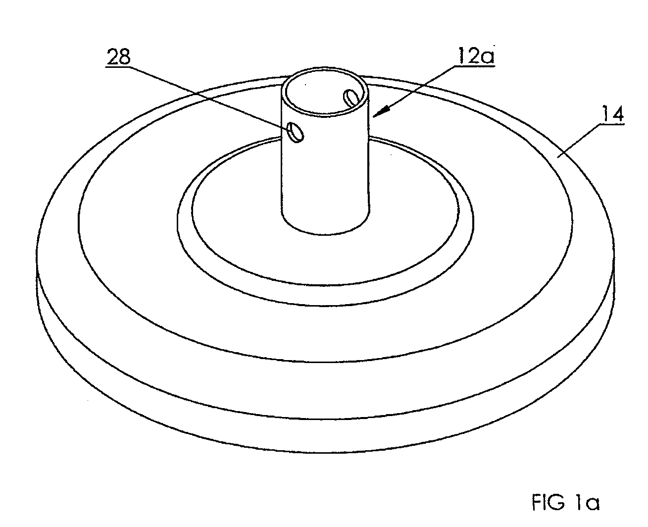
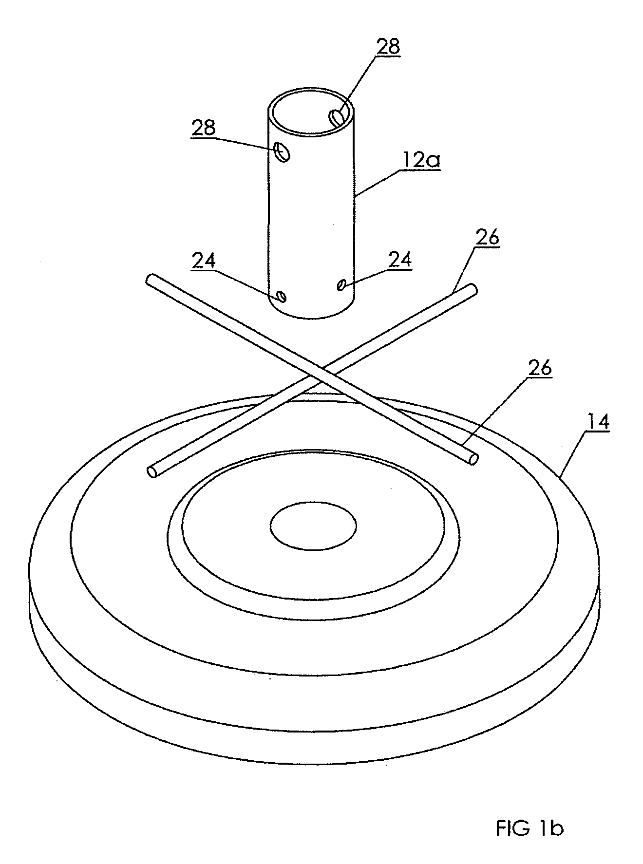
[0022]With reference to the drawings wherein similar characters of reference denote corresponding parts in each view, the load bearing stand 10 according to the present invention includes a rigid upright member 12 mounted in a wide stabilizing base 14. Upright 12 serves as a vertical extension of the base, onto the upper end of which may be mounted other supporting members depending on the load bearing application to which the stand is being put. For example, if a plurality of the load bearing stands are to support a pipe extending generally horizontally over the ground, and elevated above the ground, in one embodiment vertical extension members 16 are welded or otherwise rigidly affixed to the upright members 12 so as to elevate and support at upper ends of the vertical extension members 16 cross-members 18 onto which are mounted pipe 20. The combination of uprights 12, vertical extension members 16 and cross-members 18 may for example elevate pipe 20 up to approximately three (3) fee


PUM


Abstract

A load bearing stand which includes a concrete base and a rigid upright member having a lower-most end rigidly anchored in the base so that the lower-most end is substantially completely immersed in the base and where the upper end is adapted for rigid mounting thereon of a load supporting structure. The lower-most end of the upright member has a plurality of apertures therethrough. A corresponding plurality of rigid rods are journalled through the plurality of apertures so as to extend the rods substantially equally and oppositely from the lower-most end of the upright member and into the base to support the member. The rods and apertures are sized for snug mating of the rods through the apertures.

Description


Claims


Application Information

Patent Timeline
Owner BEASLEY DOUGLAS
Why Eureka
Try Eureka