Beam adjustment mechanism for an LED light fixture

a technology of led light fixtures and adjustment mechanisms, which is applied in the field of adjustable beam light fixtures, can solve the problems of insufficient lumen intensity for most residential and commercial uses, diffuse light patterns, and narrow beam spread generated by leds, and achieves the effect of providing adequate illumination over a broad area and not providing sufficient lumen intensity

Inactive Publication Date: 2009-09-24
COOPER TECH CO
View PDF35 Cites 93 Cited by
  • Summary
  • Abstract
  • Description
  • Claims
  • Application Information

AI Technical Summary

Benefits of technology

This patented device has two parts: One part consists of a housing with several walls made up from six rectangular frames connected together through diagonal braces called bars. These brackets hold lamps inside them while they are fixed on top of it's framework. By changing this design, different types of lights can appear wider or narrower depending upon their desired use conditions.

Problems solved by technology

This technical problem addressed in this patented text relates to improving the efficiency and effectiveness of light bulbs used in traditional lights systems without requiring excessively long hours before installation due to their limited range of angles available. Current solutions involve adding more expensive components like dichroscope plugs or mirrors to achieve wider angle coverage, which makes it difficult to fix any changes made throughout life. Additionally, current methods involving aligning reflection cats within certain areas result in nonuniformity across these areas leading to reduced brightness levels even if they were initially set correctly.

Method used


Image

  • Beam adjustment mechanism for an LED light fixture
  • Beam adjustment mechanism for an LED light fixture
  • Beam adjustment mechanism for an LED light fixture

Examples


Embodiment Construction

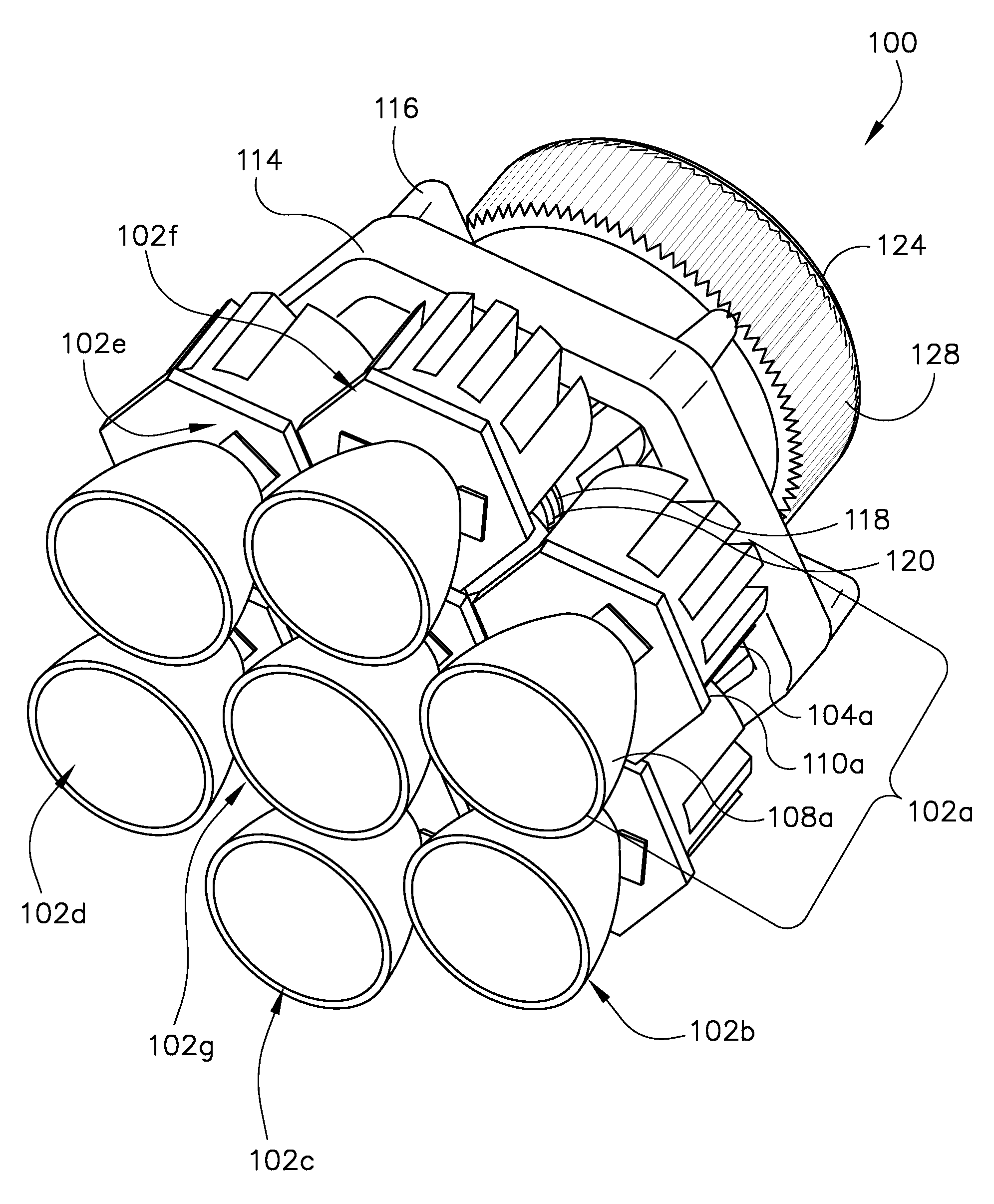
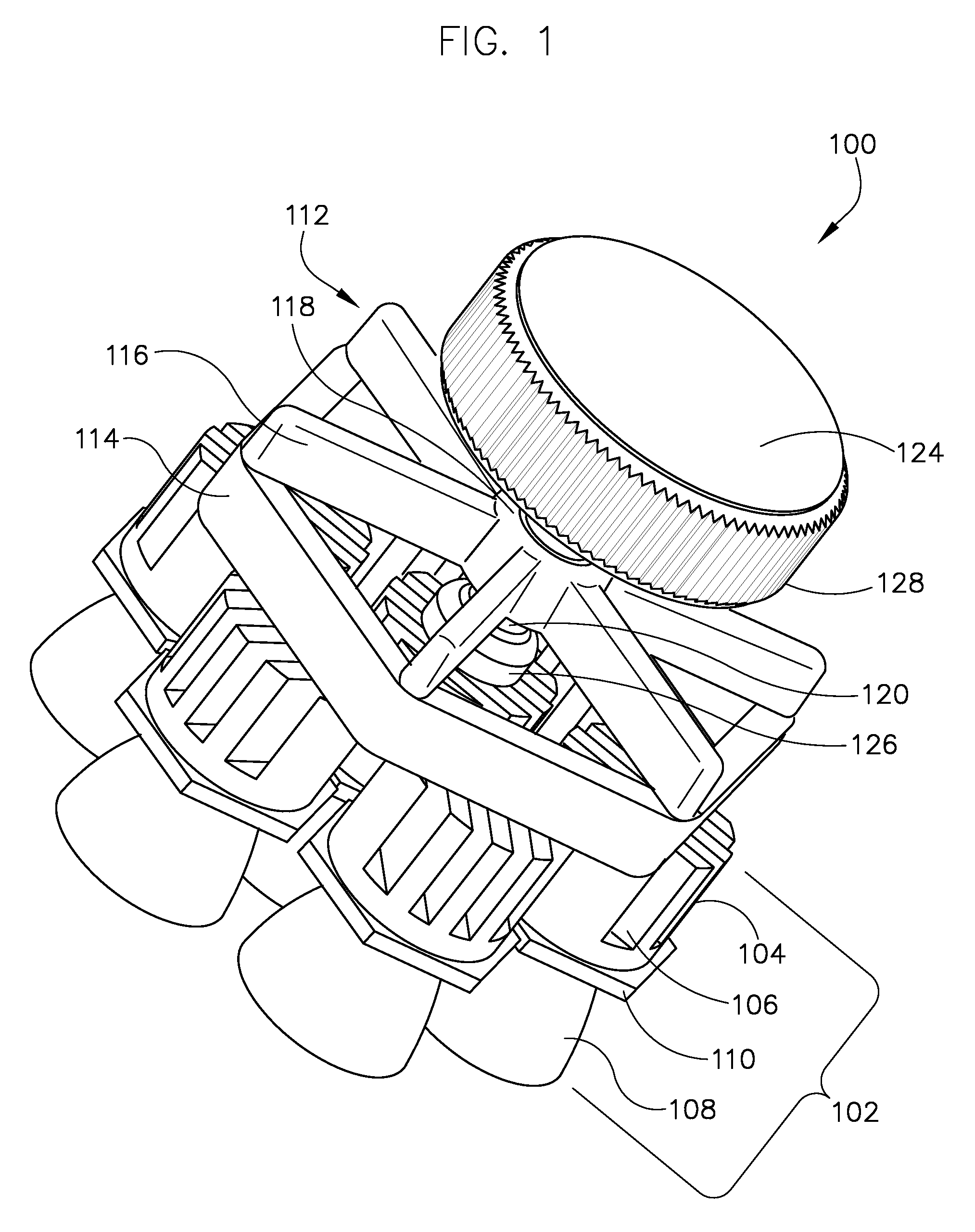
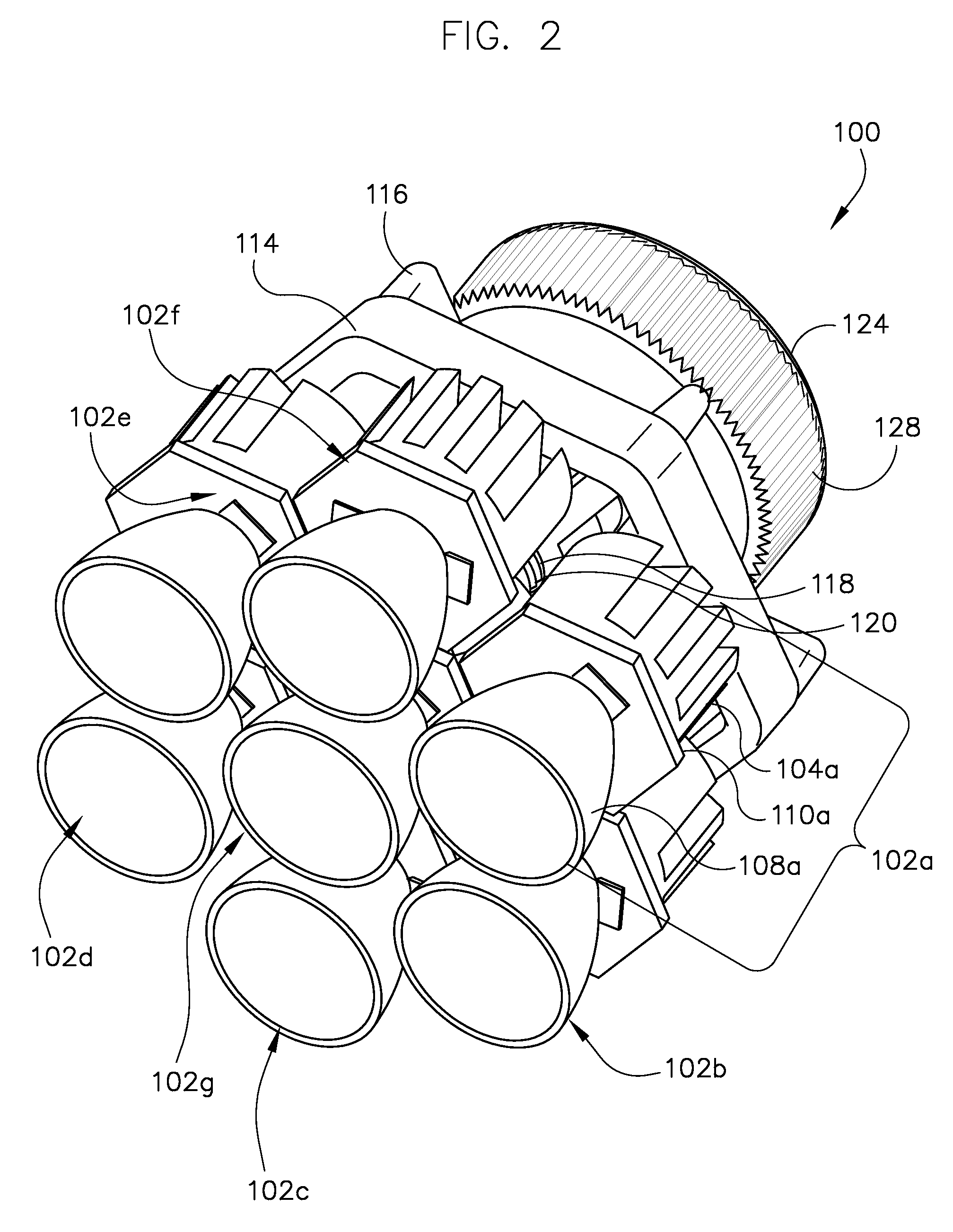
[0018]The present invention provides a beam adjustment mechanism for a light fixture capable of supporting a plurality of lighting units. The lighting units may be LEDs or LED clusters, but may also be devices that include high intensity discharge (HID) compact fluorescent bulbs, incandescent bulbs or other types of lamps. Each lighting unit may include one or more reflectors and / or lenses for directing the light produced by that lighting unit. The light fixture includes an adjustment mechanism for adjusting the direction of the light beam produced by one or more of the lighting units, such that the beams produced by the plurality of lighting units converge or diverge at a chosen distance.

[0019]As used herein, the term LED refers to a light emitting diode. The term LED cluster refers to a group of LEDs that are intended to work as a unit to provide a brighter source of illumination than a single LED. The terms LED and LED cluster may be used interchangeably herein, and refer to the u


PUM


Abstract

A beam adjustment mechanism for a light fixture includes a frame assembly having an aperture substantially within the center thereof. Multiple peripheral lighting units engage the sides of the frame assembly. Each lighting unit includes an LED, a heat sink, and a reflector member. A central connecting member and/or a central lighting unit is at least partially surrounded by the peripheral lighting units. The central connecting member and/or central lighting unit is hingedly connected to at least one of the peripheral lighting units. An adjustment shaft extends through and is moveably engaged with the aperture of the frame assembly. Movement of the adjustment shaft relative to the aperture exerts a force on the central connecting member and/or central lighting unit, which causes the hingedly connected peripheral lighting units to pivot relative to the central connecting member and/or central lighting unit.

Description


Claims


Application Information

Patent Timeline
Owner COOPER TECH CO
Why Eureka
Try Eureka