Speaker system
- Summary
- Abstract
- Description
- Claims
- Application Information
AI Technical Summary
Benefits of technology
Problems solved by technology
Method used
Image

Examples
first embodiment
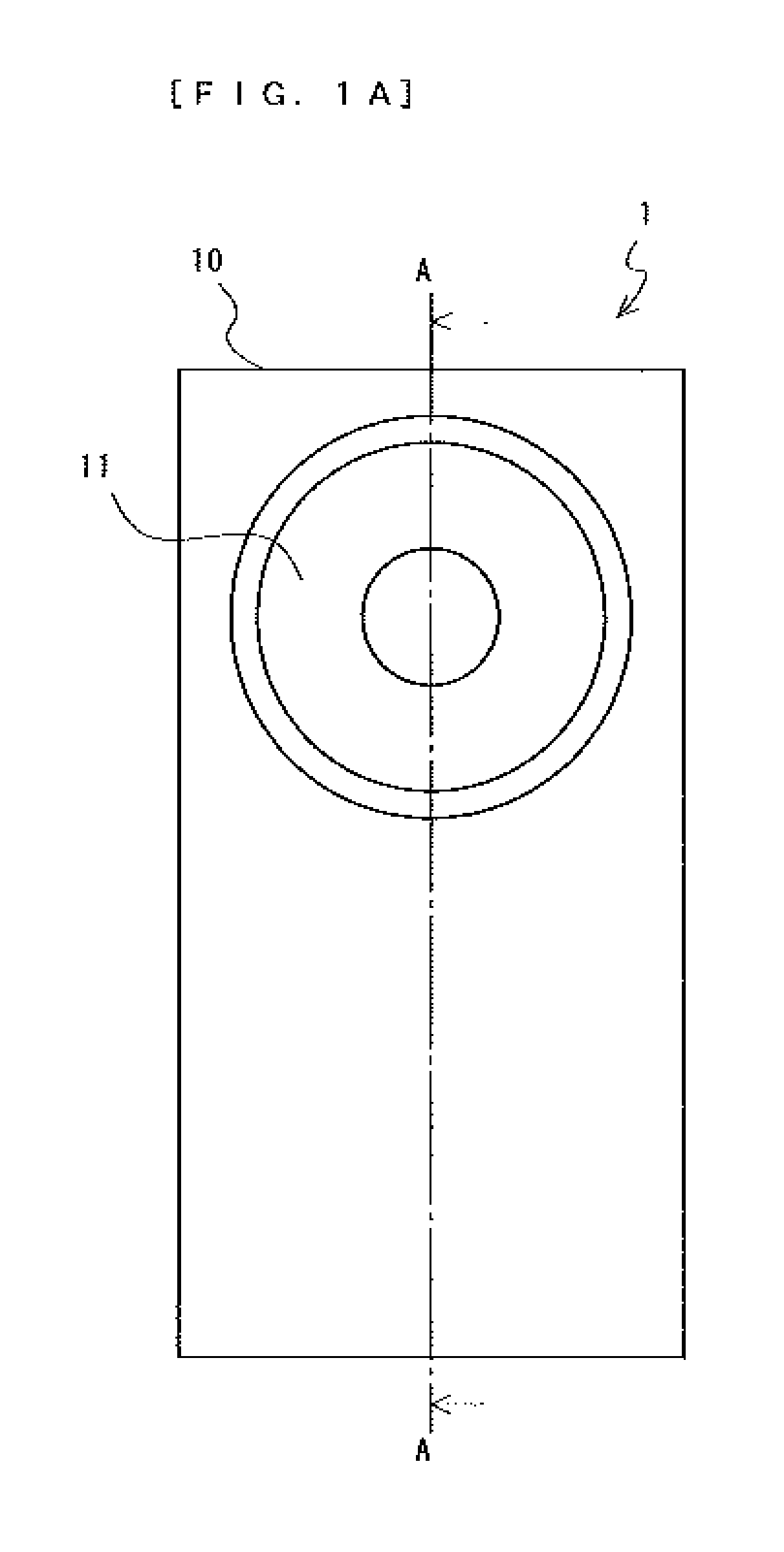
[0084]A speaker system 1 according to a first embodiment of the present invention will be described with reference to FIG. 1A and FIG. 1B. FIG. 1A is an elevation view of the speaker system 1, and FIG. 1B is a cross-sectional view illustrating the speaker system 1 along lines AA. In FIG. 1A and FIG. 1B, the speaker system 1 comprises a cabinet 10, a speaker unit 11, and a gas adsorber 12. The speaker system 1 is a sealed type speaker.
[0085]The speaker unit 11 is, for example, an electrodynamic speaker. Driving force generation means (not shown) of the speaker unit 11 includes a magnetic circuit and a voice coil. The speaker unit 11 is mounted in an opening formed on the front surface of the cabinet 10. The gas adsorber 12, which is positioned in a space R10 inside the cabinet 10, physically adsorbs gas in the space R10. The space R10 is a closed space which is formed inside the cabinet 10.
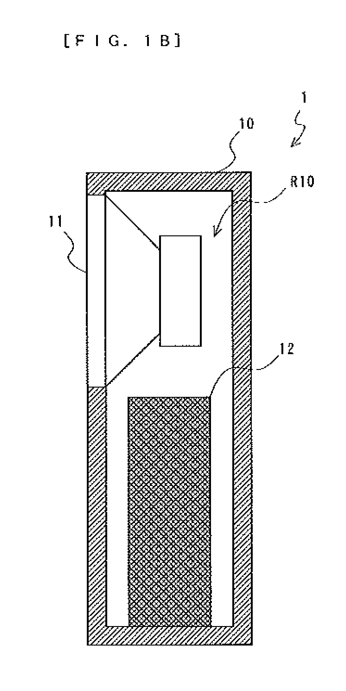
[0086]The gas adsorber 12 includes an activated carbon 121 including a plurality of grains, and a
second embodiment
[0096]A speaker system 2 of a second embodiment of the present invention will be described with reference to FIG. 3A and FIG. 3B. FIG. 3A is an elevation view of the speaker system 2, and FIG. 3B is a cross-sectional view illustrating the speaker system 2 along lines AA. In FIG. 3A and FIG. 3B, the speaker system 2 comprises a cabinet 20, a speaker unit 21, a plurality of gas adsorbers 22, and a plurality of supporting components 23. The speaker system 2 is different from the speaker system 1 of the first embodiment in that in the speaker system 2 the plurality of gas adsorbers 22 are used instead of the gas adsorber 12, and the plurality of supporting components 23 are additionally provided. Hereinafter, the different points will be mainly described.
[0097]The speaker unit 21 is, for example, an electrodynamic speaker, as in the case of the speaker unit 11. The speaker unit 21 is mounted in an opening formed on the front surface of the cabinet 20. The plurality of gas adsorbers 22 each
third embodiment
[0103]A speaker system 3 according to a third embodiment of the present invention will be described with reference to FIG. 5A and FIG. 5B. FIG. 5A is an elevation view of the speaker system 3, and FIG. 5B is a cross-sectional view illustrating the speaker system 3 along lines AA. In FIG. 5A and FIG. 5B, the speaker system 3 comprises a cabinet 30, a speaker unit 31, a gas adsorber 32, and a passive radiator 33. The speaker system 3 is different from the speaker system 1 of the first embodiment in that in the speaker system 3 the back wall of the cabinet 30 has a shape different from that of the cabinet 10, the gas adsorber 32 is used instead of the gas adsorber 12, and the speaker is a phase inversion type speaker using the passive radiator 33 instead of a sealed type speaker. Hereinafter, the different points will be mainly described.
[0104]The speaker unit 31 is, for example, an electrodynamic speaker, as in the case of the speaker unit 11. The speaker unit 31 is mounted in an opening
PUM
 Abstract
Description
Claims
Application Information
 - R&D Engineer
- R&D Manager
- IP Professional
- Industry Leading Data Capabilities
- Powerful AI technology
- Patent DNA Extraction
Browse by: Latest US Patents, China's latest patents, Technical Efficacy Thesaurus, Application Domain, Technology Topic.
© 2024 PatSnap. All rights reserved.Legal|Privacy policy|Modern Slavery Act Transparency Statement|Sitemap