Toilet plunger cleaning receptacle

Inactive Publication Date: 2009-10-22
DAVIDSON DANITA C +1
View PDF7 Cites 3 Cited by
  • Summary
  • Abstract
  • Description
  • Claims
  • Application Information

AI Technical Summary

Problems solved by technology

Typical cleaning systems for toilet brushes and toilet plungers only provide minimal disinfection of the toilet implements, generally through the application of a sanitizing solution, and are not effective at removing

Method used


Image

  • Toilet plunger cleaning receptacle
  • Toilet plunger cleaning receptacle
  • Toilet plunger cleaning receptacle

Examples


Embodiment Construction

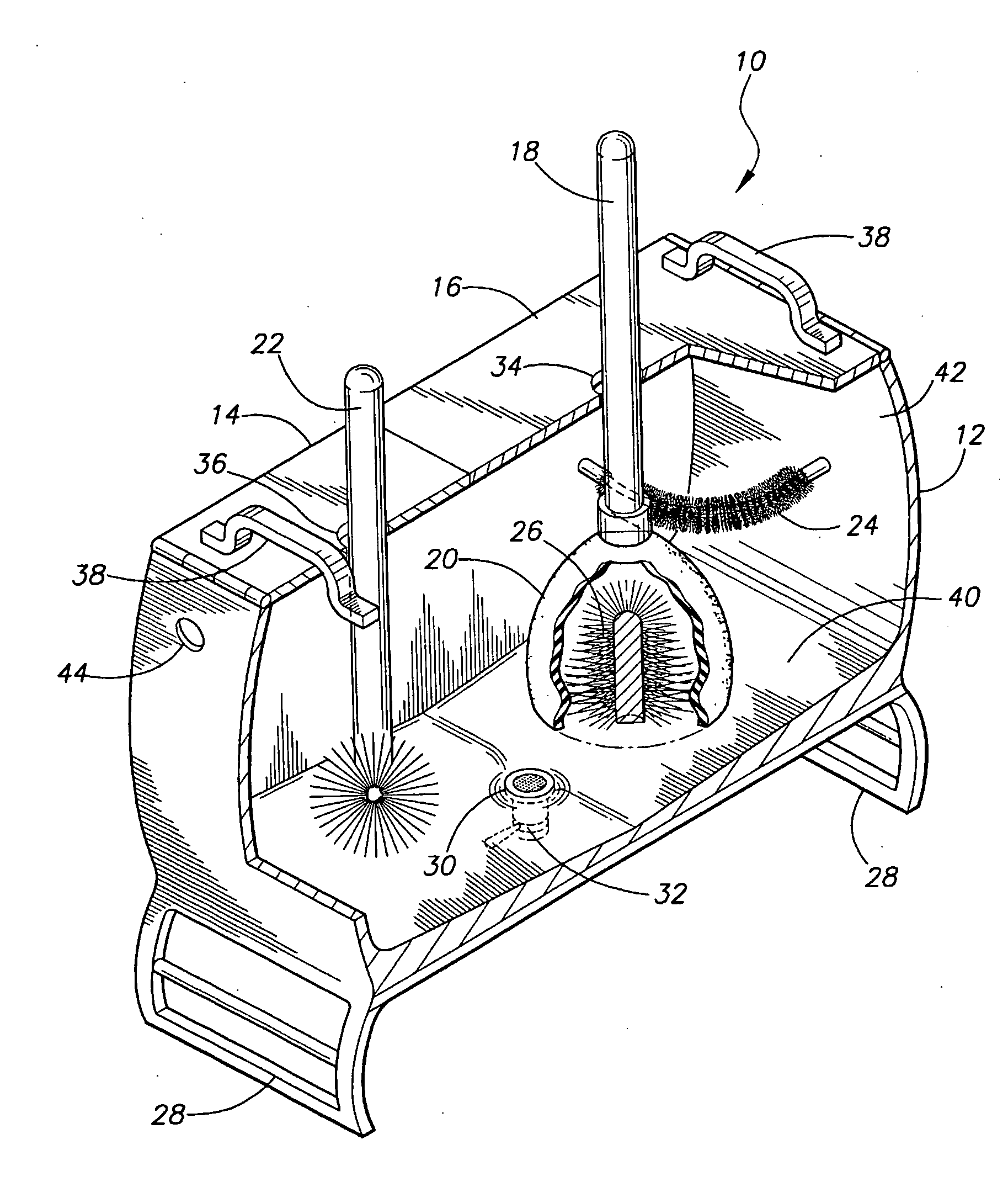
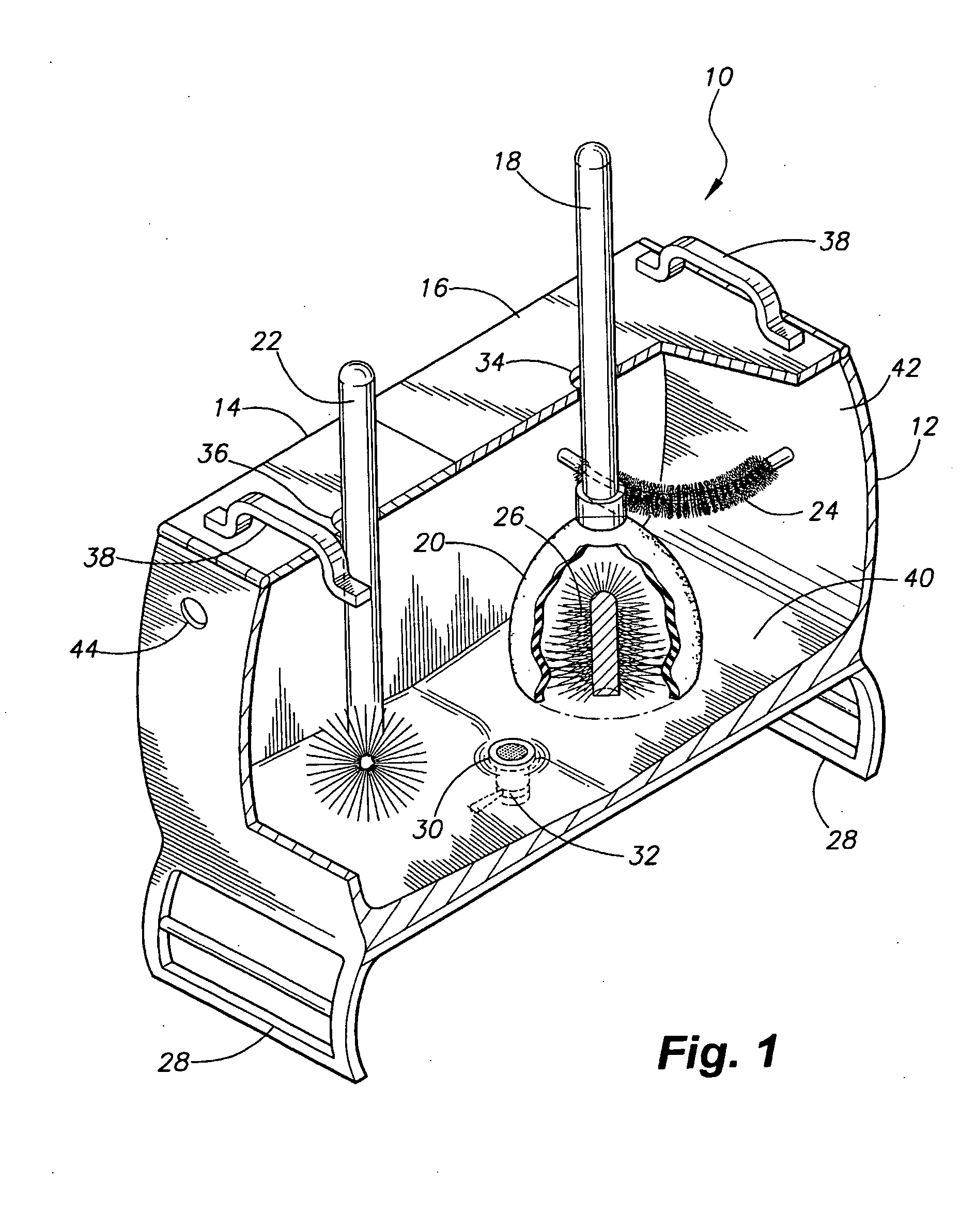
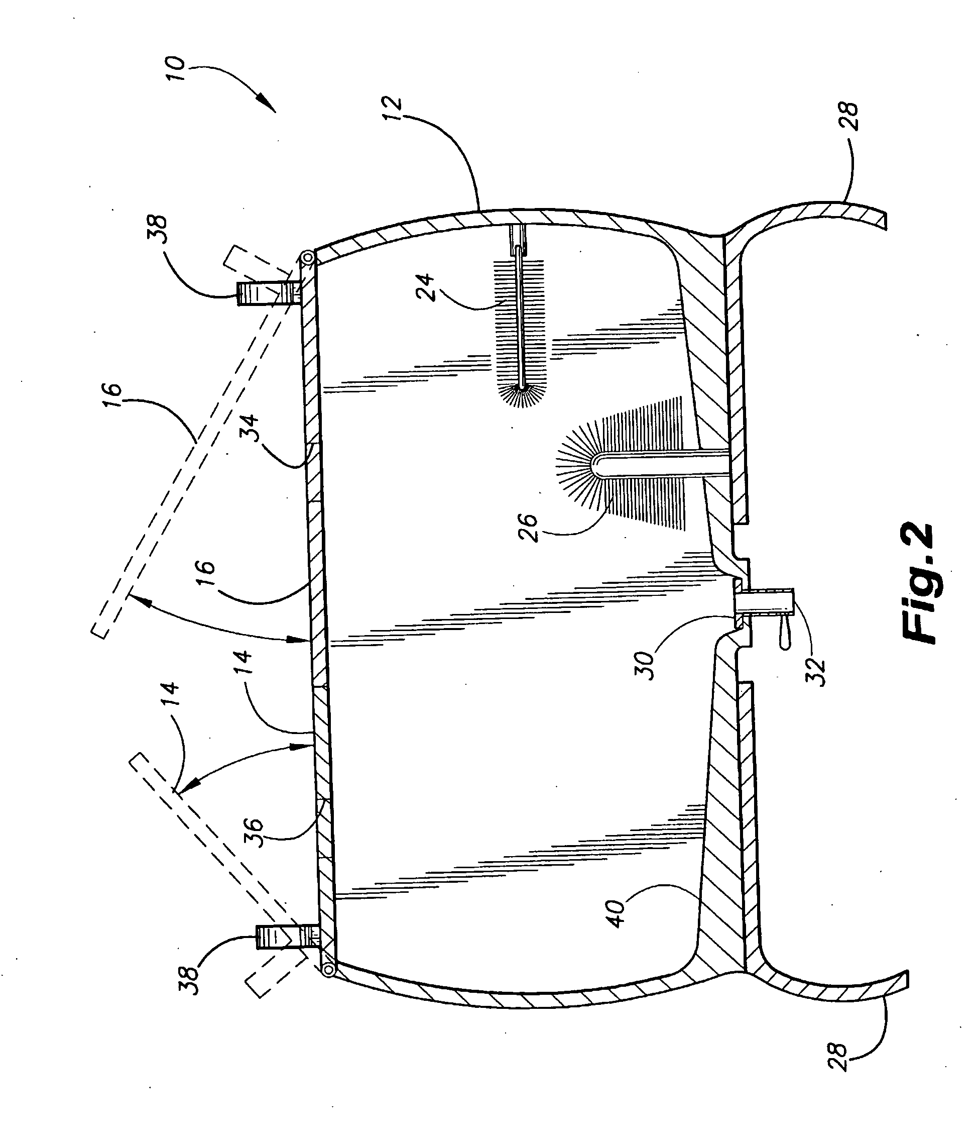
[0010]The present invention provides for a toilet plunger cleaning receptacle. The receptacle receives a sanitizing solution and includes a lower brush mounted to a lower interior surface of the receptacle, and an upper brush mounted to a sidewall of the receptacle, adjacent the lower brush. The receptacle receives a toilet plunger, and the bell of the plunger is positioned between the upper and lower brushes. Rotation of the plunger handle allows for the scrubbing of the plunger bell between the brushes. The receptacle is further designed to receive a separate toilet brush and also to hold a sanitizing solution. Both the plunger and toilet brush are immersed within the sanitizing solution to properly disinfect the toilet implements. The plunger cleaner is provided with a drain for drainage of the used sanitizing solution.

[0011]Referring now to FIGS. 1 and 2, there is shown a toilet plunger cleaning receptacle 10 of the present invention. Receptacle 10 includes a main tank 12 for recei


PUM


Abstract

The receptacle (10) includes a main receptacle tank (12) for receiving a toilet plunger (18) and a volume of sanitizing solution. The bell (20) of the plunger (18) is positioned between a lower brush (26) and an upper brush (24) so that rotation of the plunger handle abrades both the interior and exterior surfaces of the bell (20) against the upper (24) and lower (26) brushes. The tank (12) of the receptacle (10) further receives and holds a sanitizing solution to disinfect the toilet plunger (18). A pair of upper access doors (14, 16) may be provided for allowing the user access to the interior of the tank (12). A drainage hole (30) is formed through a lower surface (40) of the tank (12), allowing for the drainage of used sanitizing solution.

Description


Claims


Application Information

Patent Timeline
Owner DAVIDSON DANITA C
Why Eureka
Try Eureka