Cosmetic case

a technology for cosmetics and bags, applied in the field of cosmetic cases, can solve the problems of not having a mirror which can be stored, the inability to organize the materials stored in the bag in a manner that renders those materials readily accessible,

Inactive Publication Date: 2009-11-05
ANNE MARIE K ORIGINALS
View PDF53 Cites 19 Cited by
  • Summary
  • Abstract
  • Description
  • Claims
  • Application Information

AI Technical Summary

Benefits of technology

This patented design allows multiple items can be stored on top within a compact space while still being able to easily access them through pivotally mounted flip-up panels that allow easy movement around inside it's housing.

Problems solved by technology

The technical problem addressed by this patented technology relates to creating a small-scale case or box where multiple storage areas may exist within it without requiring manual handling during conversion between different positions. This would allow users to efficiently manage their collections while also being affordably made lighter than traditional carrying bulky boxes.

Method used


Image

  • Cosmetic case
  • Cosmetic case
  • Cosmetic case

Examples


Embodiment Construction

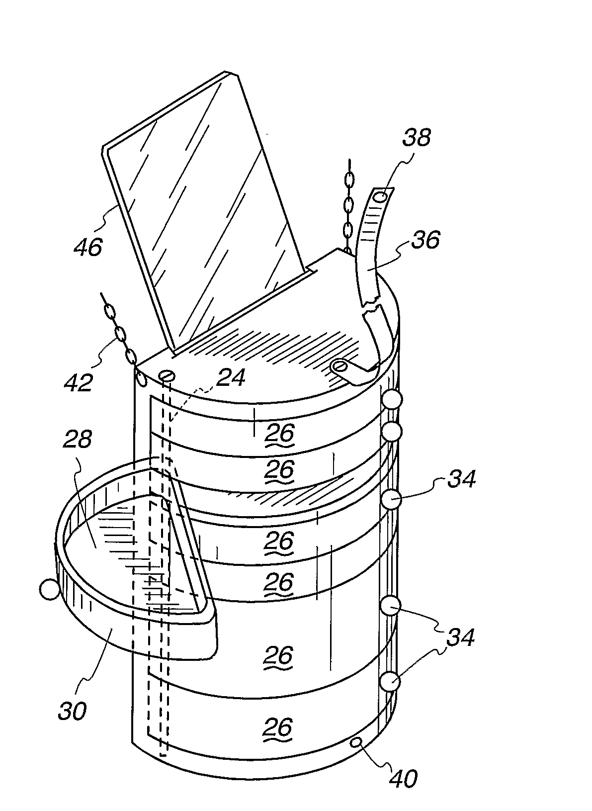
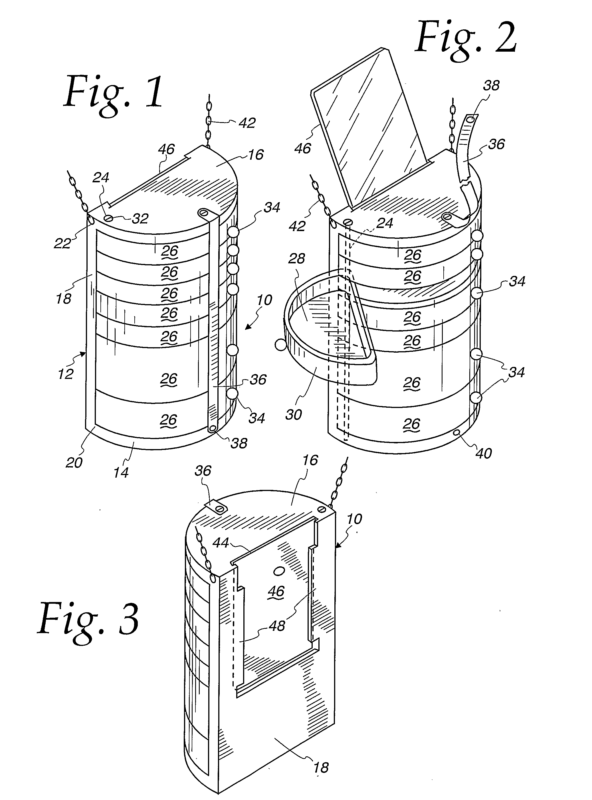
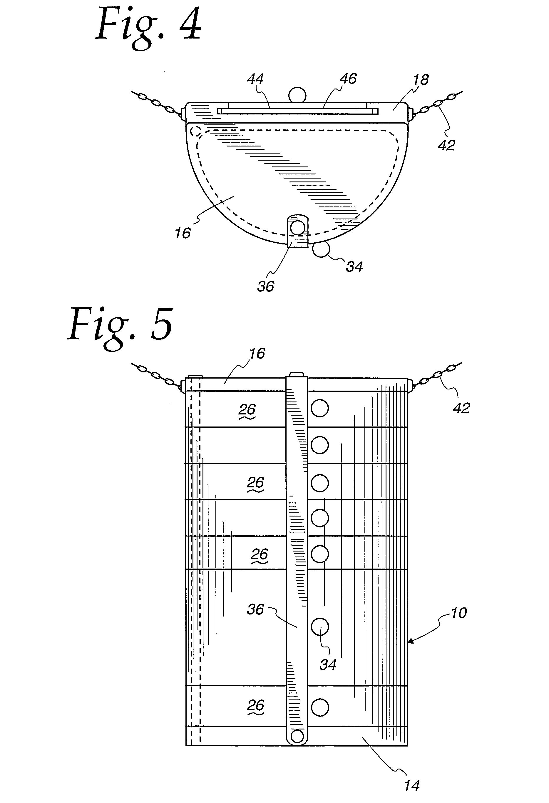
[0034]FIGS. 1-9 show an embodiment 10 of a cosmetic case of the present invention. The cosmetic case 10 comprises a base frame 12 that includes a lower portion 14, an upper portion 16 and a mid- (or medial or back) portion 18. The back portion 18 extends between the respective opposed rear edges 20 and 22 of the lower portion 14 and the upper portion 16. The lower portion 14 and the upper portion 16 are each preferably flat and preferably have similar perimeters. Preferably they extend in vertically spaced, parallel relationship relative to each other although diagonal but parallel arrangements can be used if desired. The back portion 18 is preferably flat and preferably extends perpendicularly between the lower portion 14 and the upper portion 16 although the back portion can extend diagonally between the portions 14 and 16 if desired. Preferably the back portion 18 has a perimeter that defines a parallelogram with upper and lower edge portions that are in spaced, parallel relationshi


PUM

PropertyMeasurementUnit
Contentaaaaaaaaaa

Abstract

A cosmetic case is provided that includes a frame and a plurality of interleaved, vertically tiered compartments for the storage of cosmetics or other items. The compartments of the plurality are independent and can pivot laterally to an open position. The case is provided with a mirror which can occupy either a storage position or a viewing position. The mirror storage position can be located in the frame or in a compartment, preferably an uppermost compartment that is hinged on a horizontal axis. The case includes a pair of pivot shafts enabling selected compartments to pivot in an opposed lateral direction to an open position so that more than one compartment can be readily opened for concurrent display of their contents.

Description


Claims


Application Information

Patent Timeline
Owner ANNE MARIE K ORIGINALS
Why Eureka
Try Eureka