Adjustable ratchet

a ratchet and adjustable technology, applied in the field of ratchets, can solve the problems of inconvenient use of the type of ratchet wrenches

Inactive Publication Date: 2009-11-12
STANLEY WORKS THE
View PDF51 Cites 3 Cited by
  • Summary
  • Abstract
  • Description
  • Claims
  • Application Information

AI Technical Summary

Benefits of technology

The technical effect described by these inventions is improved efficiency during production compared to existing structures or components. These improvements can lead to better performance at reduced costs while still maintaining their desired properties.

Problems solved by technology

The technical problem addressed in this patented text relating to current types of ruler-heads used for driving fastening tools such as screw drivers has its limitations when it needs to change from small bolts to larger ones due to their large number of required bits needed by multiple tool settings.

Method used


Image

  • Adjustable ratchet
  • Adjustable ratchet
  • Adjustable ratchet

Examples


Embodiment Construction

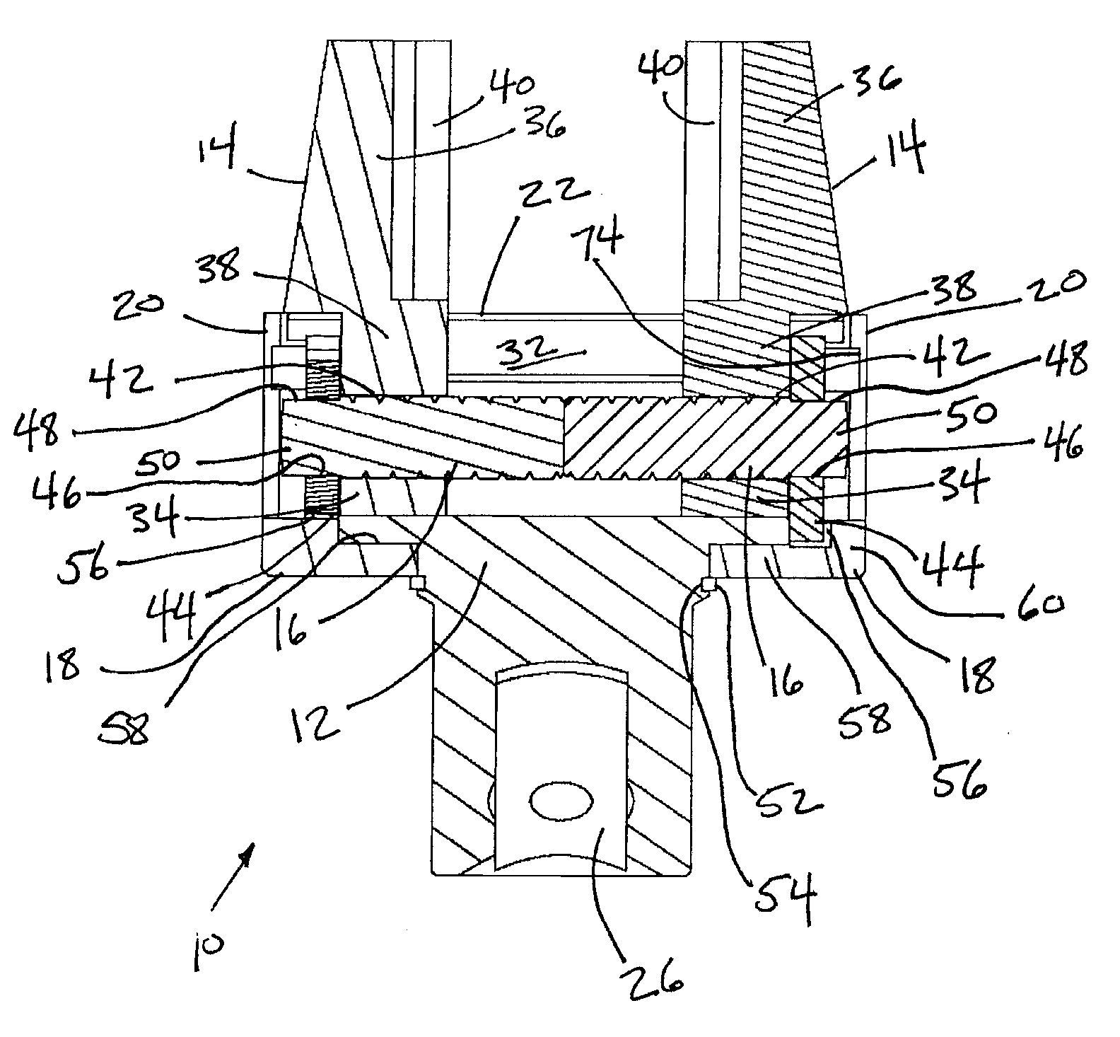
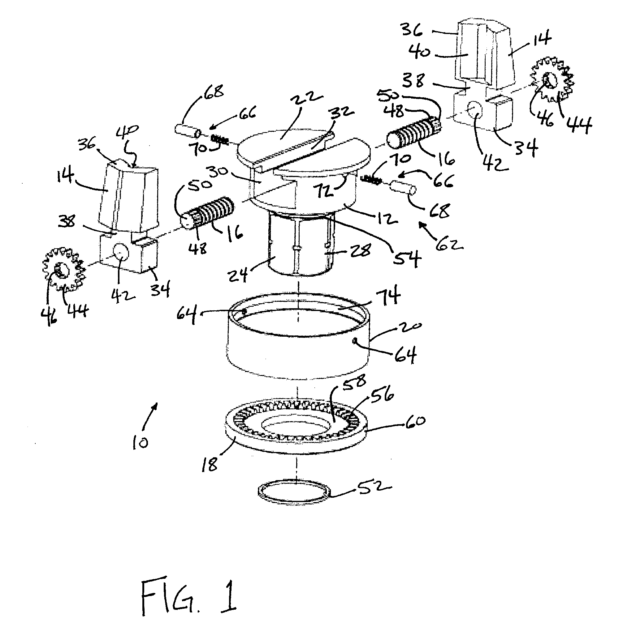
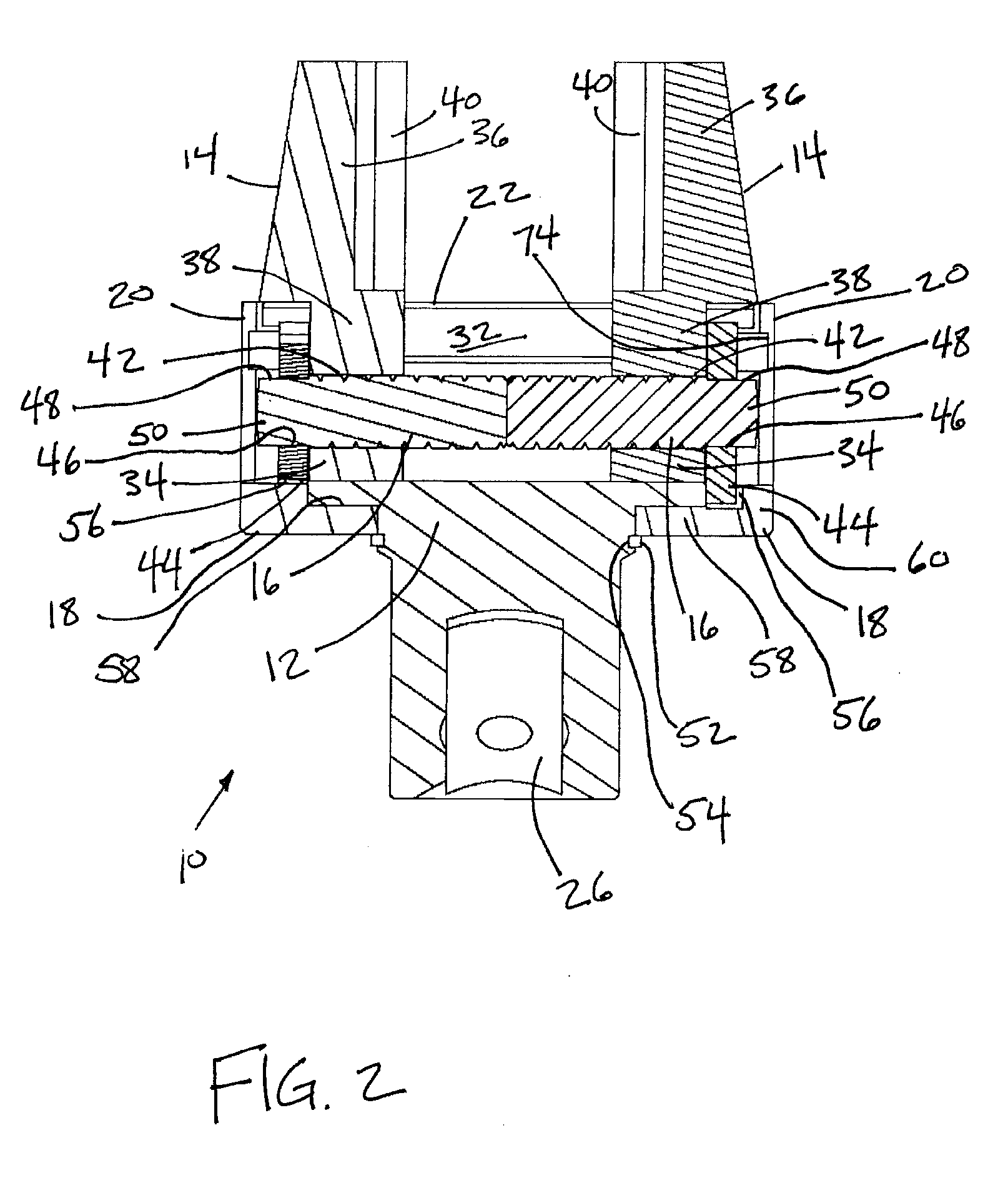
[0009]FIG. 1 illustrates an exploded perspective view of a wrench head 10, in accordance with one or more embodiments of the invention. When assembled (e.g., as shown in FIGS. 2 and 3, discussed below), wrench head 10 may form part of a wrench configured to engage a fastener and drive the fastener rotationally. As can be seen in FIG. 1, wrench head 10 includes a base 12, a pair of jaws 14, a pair of threaded shafts 16, an adjusting ring 18, and a sleeve 20.

[0010]In one embodiment, base 12 runs longitudinally between a face 22 on one end and a drive body 24 formed toward the end of base 12 opposite face 22. Face 22 includes one or more surfaces that are oriented toward a fastener, if the fastener is engaged by wrench head 10. More particularly, in some instances, face 22 includes one or more surfaces that are substantially orthogonal to an axis of rotation about which wrench head 10 drives the fastener. Drive body 24 is formed to be engaged by a handle (not shown) to drive wrench head 1


PUM


Abstract

A wrench is configured to engage a fastener for rotation. In one embodiment, the wrench comprises a base, a pair of jaws, a pair of threaded shafts, an adjusting ring, and/or a sleeve. The position of the pair of jaws along the base may be adjustable to accommodate fasteners of different sizes.

Description


Claims


Application Information

Patent Timeline
Owner STANLEY WORKS THE
Why Eureka
Try Eureka