Mini Receptacle

a technology of conductive terminals and receptacles, applied in the direction of coupling device connections, coupling protective earth/shielding arrangements, electric discharge lamps, etc., can solve the problems of short circuit failure, conductive terminal portions are still prone to contact, short circuit may occur, etc., and achieve the effect of preventing short circuit failur

Active Publication Date: 2010-08-19
MOLEX INC
View PDF1 Cites 12 Cited by
  • Summary
  • Abstract
  • Description
  • Claims
  • Application Information

AI Technical Summary

Benefits of technology

The present invent describes how it prevents damage caused during use due to improperly bent or touch-contacting electrical connectors used for signal transmission purposes. This helps ensure reliable connections are achieved even if there may have been any impact on them over time.

Problems solved by technology

This patented technical problem addressed by the present inventor relates to improving the design for prevention of short circuits caused by touch-to-contact during use of electric connectors.

Method used


Image

  • Mini Receptacle
  • Mini Receptacle
  • Mini Receptacle

Examples


Embodiment Construction

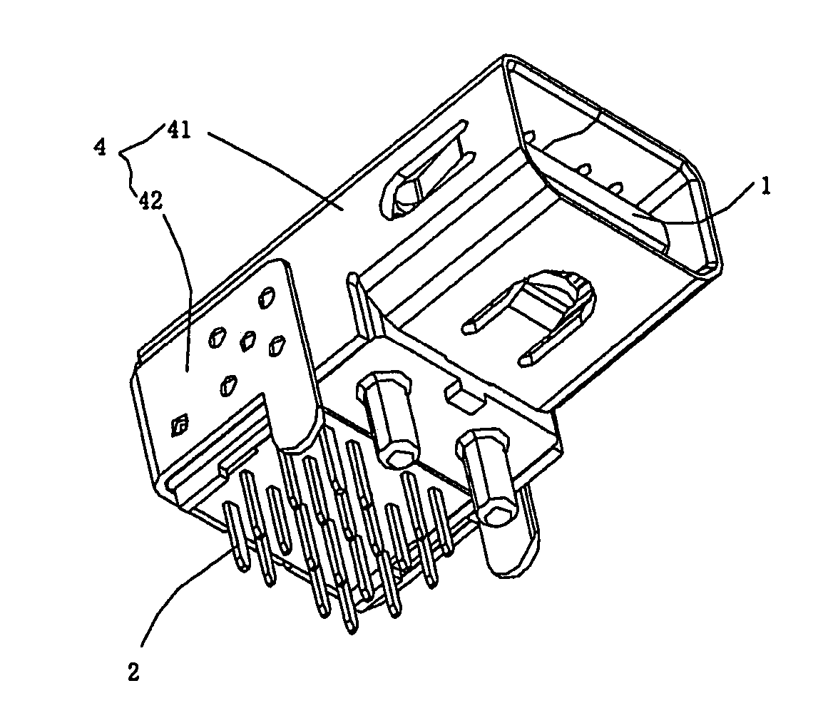
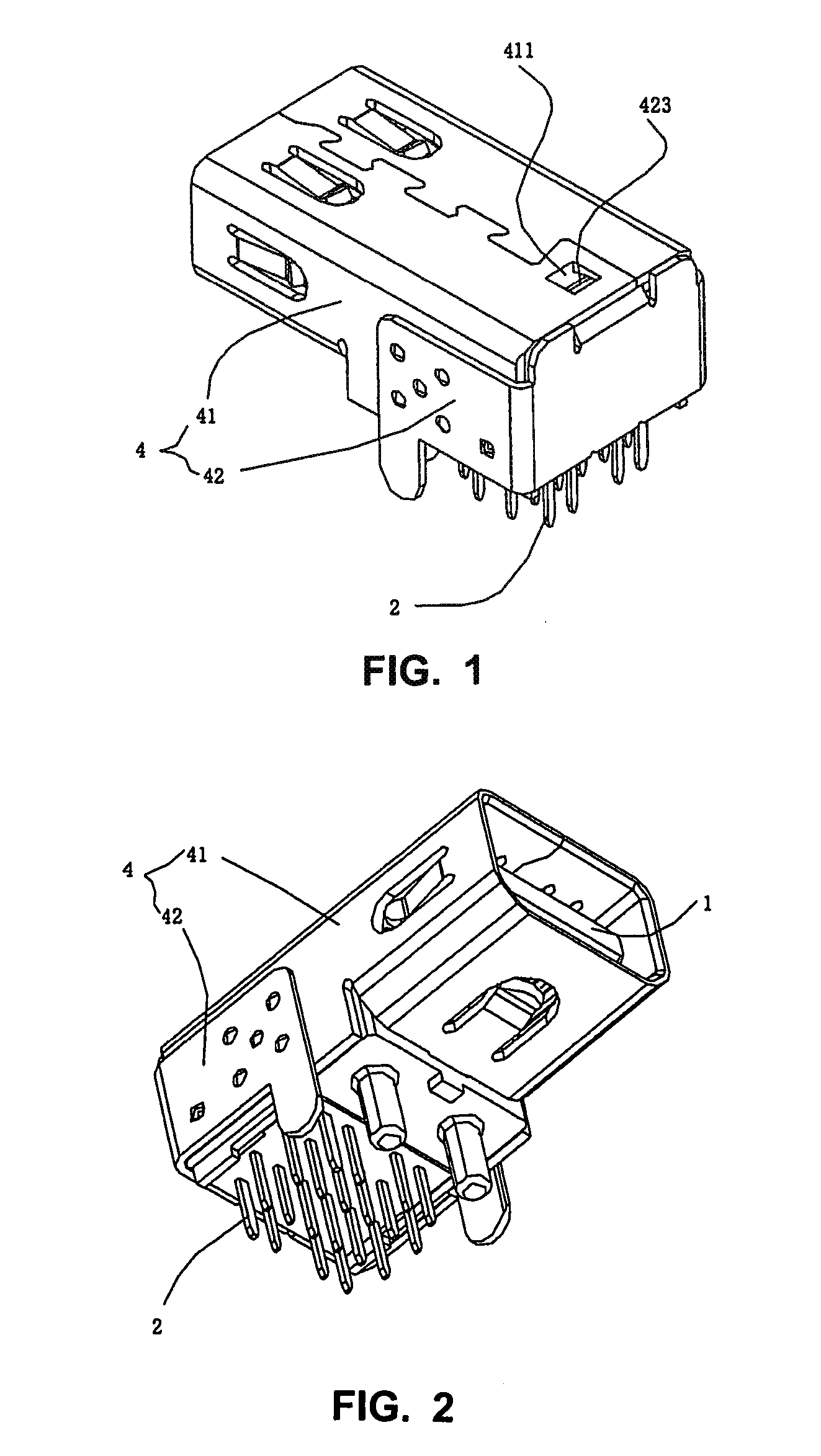
[0024]The present invention will be described in detail with reference to the drawings, by taking the Mini-Displayport electrical connector as an example.

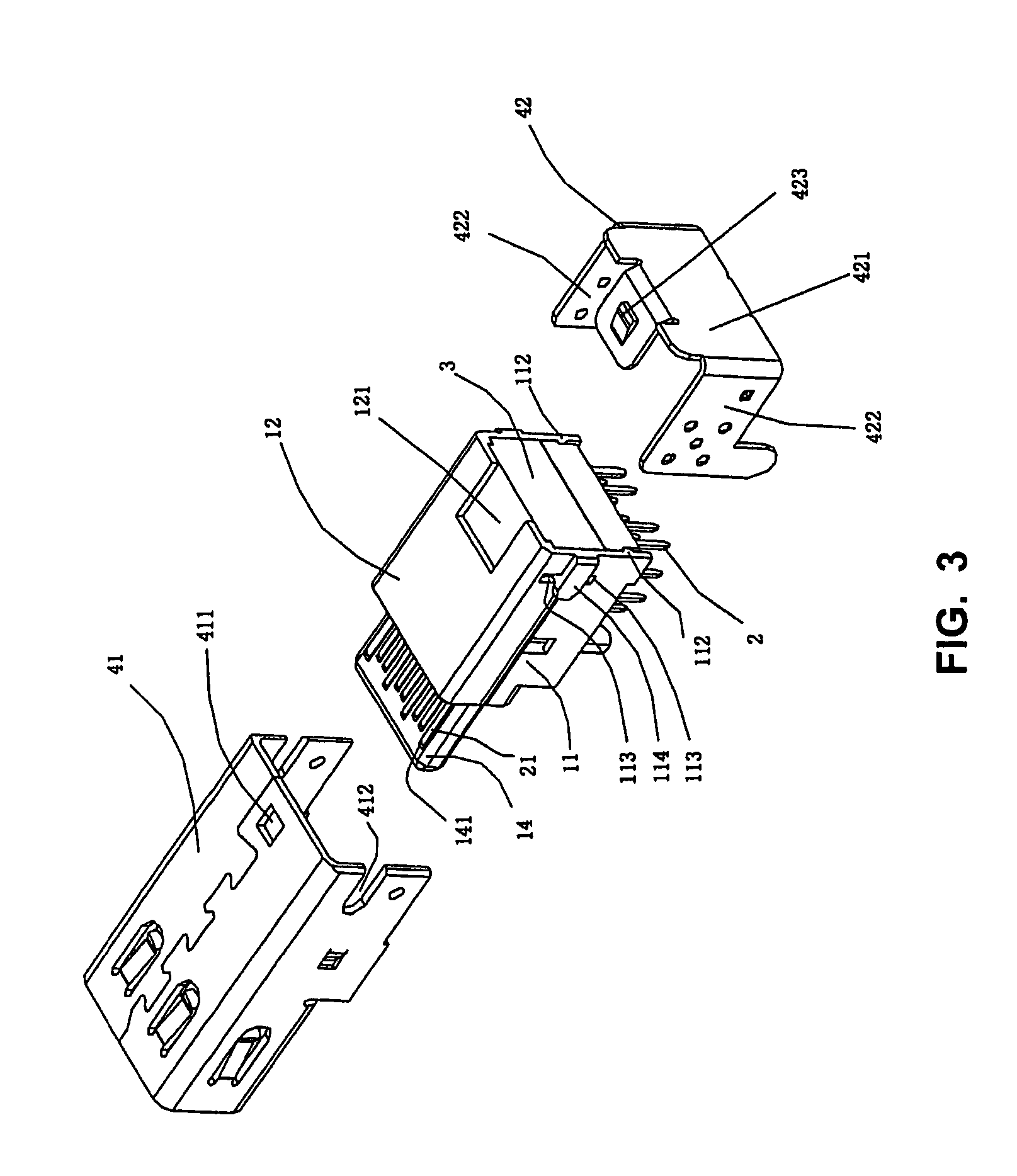
[0025]As shown in FIGS. 1 to 4, an electrical connector according to a preferred embodiment of the present invention comprises an insulating housing 1, a plurality of conductive terminals 2 fitted on the insulating housing 1, a positioning module 3 for fixing the plurality of conductive terminals 2, a spacer plate 34, and a shielding casing 4.

[0026]Referring to FIGS. 5 and 6, an accommodating chamber 13 is provided at the rear portion of the insulating housing, which is formed by two sidewalls 11 and a top wall 12, and a tongue plate 14 is protruded forwards from the front portion of the insulating housing 1. A plurality of terminal receiving grooves 141 are provided at both of the upper and lower sides of the tongue plate 14, which penetrate through the insulating housing 1 from front to rear. Both of the inner surfaces of two sidewa


PUM


Abstract

An electrical connector comprises: an insulating housing having an accommodating chamber at a rear portion thereof and a tongue plate protruding forwards from a front portion thereof; a plurality of conductive terminals comprising an upper row of conductive terminals and a lower row of conductive terminals which are mounted on upper and lower sides of the tongue plate respectively, each conductive terminal including a butting portion, a soldering portion, and a bending portion connected between the butting portion and the soldering portion, the butting portions of said upper row of conductive terminals and lower row of conductive terminals being mounted on the upper and lower sides of the tongue plate respectively, the soldering portions of each row of conductive terminals extending from below the rear portion of the insulating housing and being arranged in a front column and a rear column; a shielding casing covering periphery of the insulating housing; and two positioning modules being mounted into the accommodating chamber of the insulating housing and enveloping periphery of the bending portions of said plurality of conductive terminals. The electrical connector can efficiently prevent bending portions of the conductive terminals from further bending and contacting with each other when an external force is applied and thus can prevent the short circuit failure.

Description


Claims


Application Information

Patent Timeline
Owner MOLEX INC
Why Eureka
Try Eureka