Reducing Foulant Carry-Over or Build Up In A Paraffinic Froth Treatment Process
a paraffinic froth treatment and foulant technology, applied in the direction of hydrocarbon oil treatment, liquid hydrocarbon mixture production, corrosion/fouling inhibition of treatment apparatus, etc., can solve the problems of foulant build-up to a thickness, interfere with the normal operation of the process, etc., to reduce downstream foulant carry-over, reduce fouling, and reduce the effect of build-up in the vessel
- Summary
- Abstract
- Description
- Claims
- Application Information
AI Technical Summary
Benefits of technology
Problems solved by technology
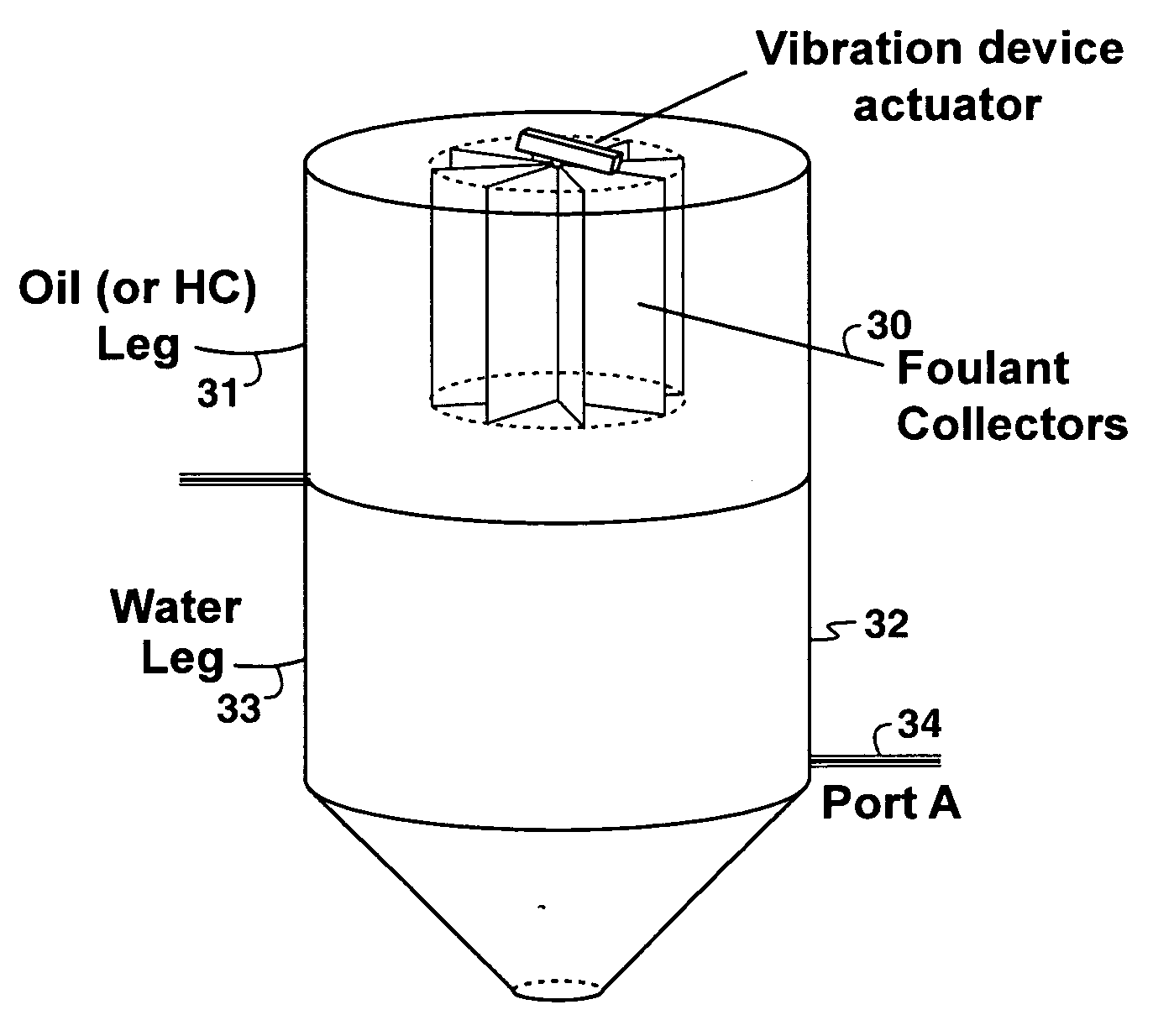
Method used
Image

Examples
example 1
Carbon Steel, Cement, and Ceramic Materials in FSU-1
[0079]Three materials: carbon steel, cement and a ceramic (Kalceram™, from Abresist Corporation, Urbana, Ind.) were evaluated as small coupons made from each material.
[0080]Each coupon was suspended by a steel wire from the top of the settler pipe section in FSU-1 (FIG. 4a). After being exposed continuously to the FSU-1 hydrocarbon over a period of 72 hours, all three coupons collected a significant amount of foulant.
[0081]This example shows that all three of these materials collected foulant that would otherwise be carried over downstream.
example 2
Carbon Steel, Cement and Ceramic Materials in FSU-2
[0082]Five materials: carbon steel, three ceramics (Abresist™, Alresist™ and Kalceram™, all from Abresist Corporation, Urbana, Ind.) and cement were evaluated in FSU-2. The coupons from these materials are shown in FIG. 5a before the run. After a 72-hour run, all the coupons collected a significant amount of foulant (FIG. 5b).
[0083]Each material was successful in collecting foulant material from the FSU-2 hydrocarbon stream, thereby demonstrating its effectiveness in reducing foulant build-up and carry-over to the equipment, conduits and vessels downstream of the FSU-2.
[0084]The higher amount of foulant build-up in all the FSU-2 coupons compared to FSU-1 coupons is evident when FIG. 5b in Example 2 is compared with FIG. 4b in Example 1. This is also evident when the carbon-steel coupon from FSU-2 (FIG. 6b) is compared with that from FSU-1 (FIG. 6a).
[0085]The friable nature of the foulant is also evident from FIGS. 6a and 6b, as some of
example 3
Repeat Evaluation of Materials of Example 1 and 2, in FSU-1 and FSU-2
[0088]This example shows the results from the repeat tests of those in Examples 1 and 2. The coupon materials and the exposure time of 72-hour in the repeat tests were the same as those in Examples 1 and 2. The weight gains by the coupons in the repeat tests are shown in FIG. 8.
[0089]The reproducibility in the weight gain by the coupons (by comparing FIG. 8 with FIG. 7) was reasonable in view of the fact that some foulant might have fallen off because of the friable nature of the foulant. As in Examples 1 and 2, all of the materials evaluated in the repeat tests collected foulant, with the Abresist™ showing the most collection, followed by carbon steel. The Alresist™ coupon in the repeat test showed weight gain which was in line with those by the other coupons, confirming the hypothesis that its relatively lower weight gain in Example 2 was due to some of the foulant falling off prior to weighing. Consistent with Exam
PUM
 Abstract
Description
Claims
Application Information
 - R&D Engineer
- R&D Manager
- IP Professional
- Industry Leading Data Capabilities
- Powerful AI technology
- Patent DNA Extraction
Browse by: Latest US Patents, China's latest patents, Technical Efficacy Thesaurus, Application Domain, Technology Topic.
© 2024 PatSnap. All rights reserved.Legal|Privacy policy|Modern Slavery Act Transparency Statement|Sitemap