Detecting device for fuel injector
a detection device and fuel injector technology, applied in the direction of machines/engines, electrical control, instruments, etc., to achieve the effect of improving the computation accuracy of fuel pressure or fuel temperatur
- Summary
- Abstract
- Description
- Claims
- Application Information
AI Technical Summary
Benefits of technology
Problems solved by technology
Method used
Image

Examples
first embodiment
[0020]A sensor system is applied to an internal combustion engine (diesel engine) having four cylinders #1-#4.
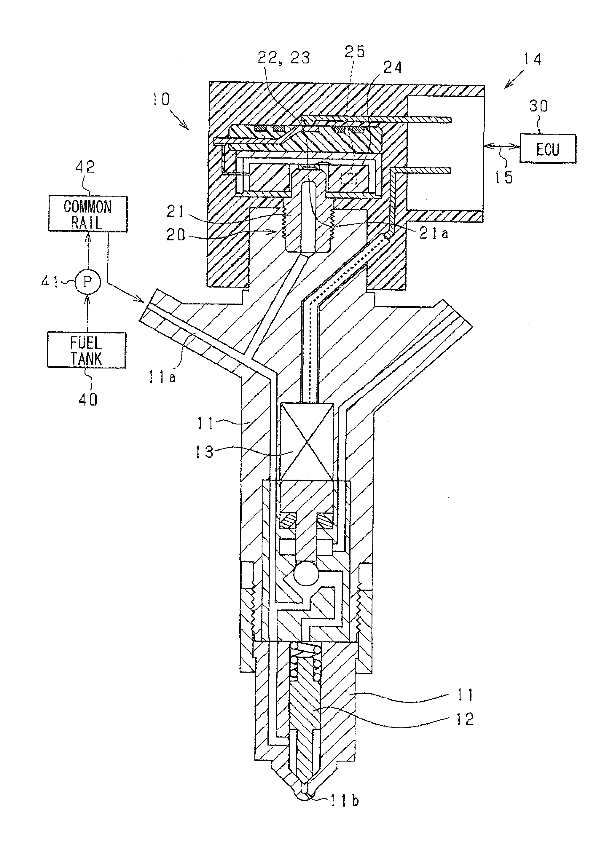
[0021]FIG. 1 is a schematic view showing a fuel injector 10, a sensor unit 20, an electronic control unit (ECU) 30 and the like.
[0022]First, a fuel injection system of the engine including the fuel injector 10 will be explained. A fuel in a fuel tank 40 is pumped up by a high-pressure pump 41 and is accumulated in a common rail 42 to be supplied to each cylinder.
[0023]The fuel injector 10 is comprised of a body 11, a needle (valve body) 12, an actuator 13 and the like. The body 11 defines a high pressure passage 11a and an injection port 11b. The needle 12 is accommodated in the body 11 to open / close the injection port 11b. The actuator 13 drives the needle 12.
[0024]The ECU 30 controls the actuator 13 to drive the needle 12. When the needle 12 opens the injection port 11b, high-pressure fuel in the high pressure passage 11a is injected to a combustion chamber (not shown) of t
second embodiment
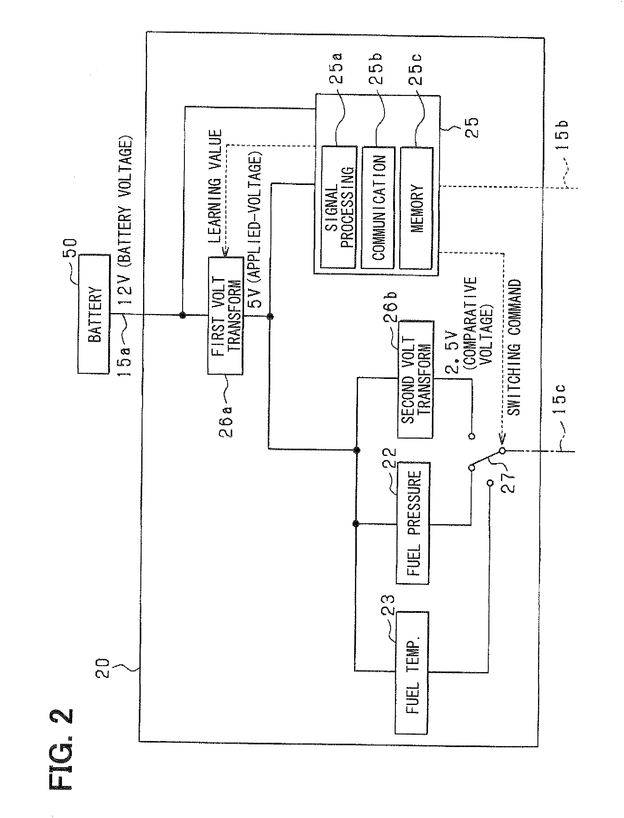
[0072]In the above first embodiment, the first voltage transform circuit 26a adjusts the applied-voltage to the reference voltage based on the deviation between the comparative voltage and the reference voltage, so that the deviation between the detected fuel pressure or fuel temperature and the actual fuel pressure or fuel temperature is decreased. According to the second embodiment, the detection signal is corrected based on the deviation between the comparative voltage and the reference voltage before the above computation.
[0073]Referring to FIGS. 6 and 7, the second embodiment will be described in detail, hereinafter.
[0074]The ECU 30 has a memory in which the correction value of the detection signal is stored. As shown in FIG. 6, the IC-chip 25 has no memory and the first voltage transform circuit 26a does not vary the adjust voltage.
[0075]Referring to FIG. 7, a computation procedure of the fuel pressure and the fuel temperature will be described. The processes in steps S10, S11, S
PUM
 Abstract
Description
Claims
Application Information
 - R&D Engineer
- R&D Manager
- IP Professional
- Industry Leading Data Capabilities
- Powerful AI technology
- Patent DNA Extraction
Browse by: Latest US Patents, China's latest patents, Technical Efficacy Thesaurus, Application Domain, Technology Topic.
© 2024 PatSnap. All rights reserved.Legal|Privacy policy|Modern Slavery Act Transparency Statement|Sitemap