Ultrasound diagnosis apparatus and method of setting sound velocity
- Summary
- Abstract
- Description
- Claims
- Application Information
AI Technical Summary
Problems solved by technology
Method used
Image

Examples
first embodiment
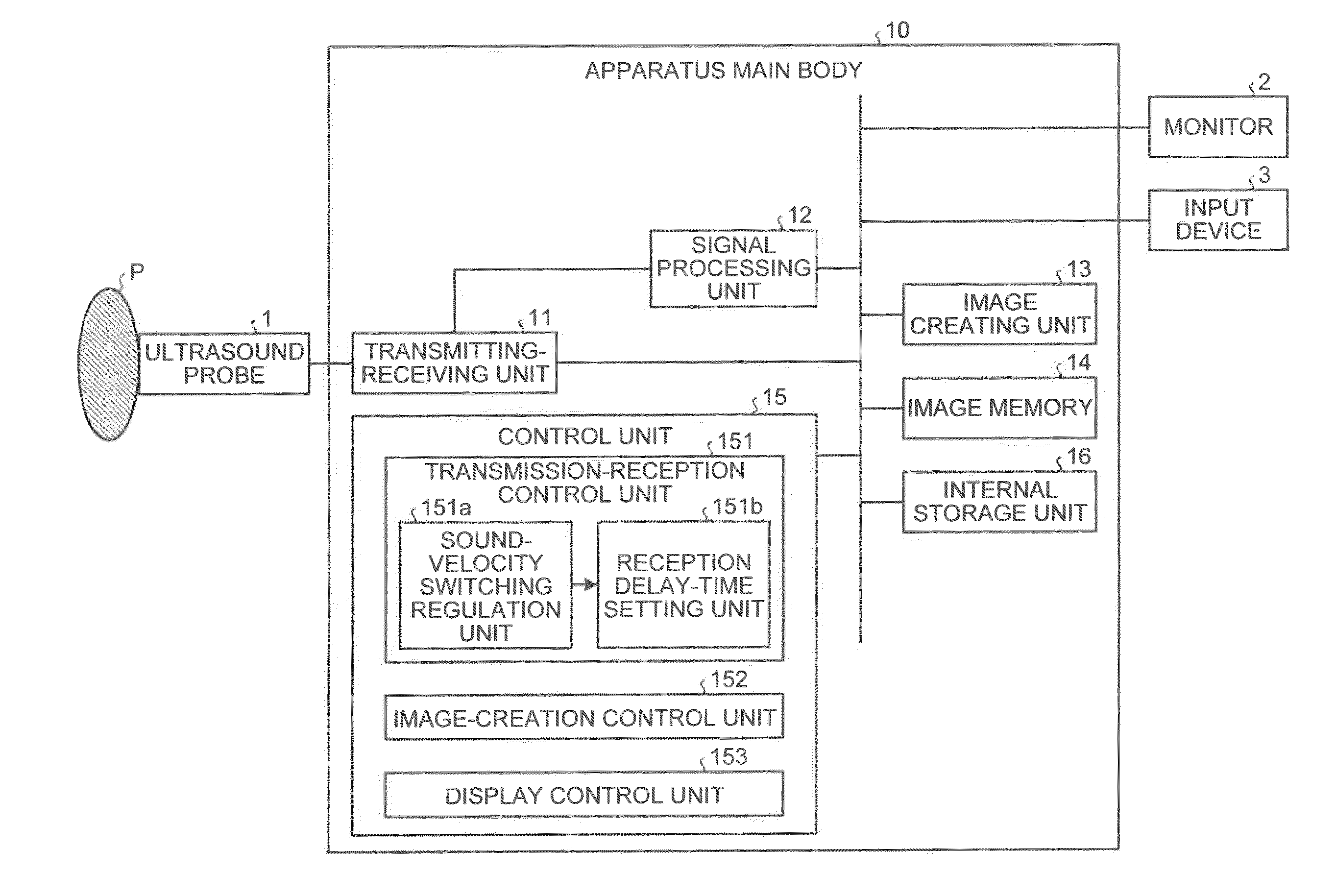
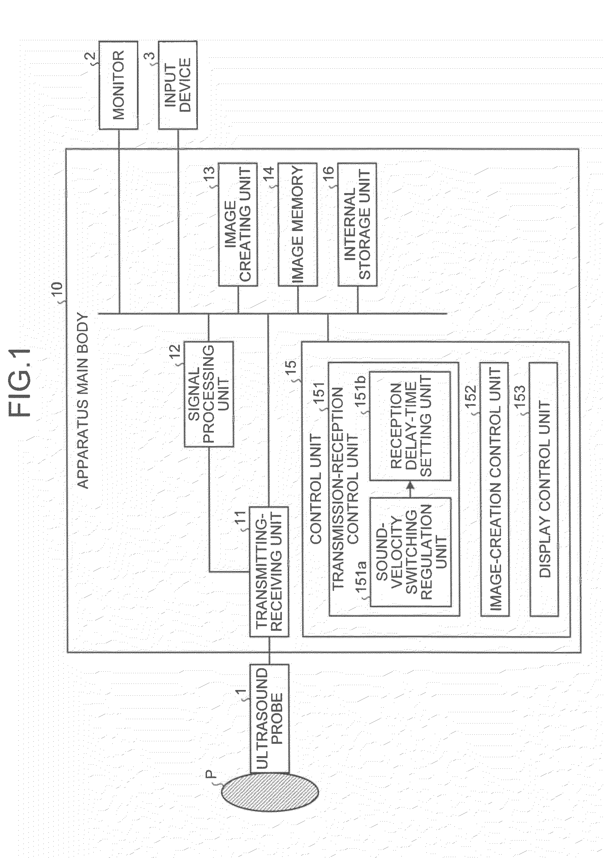
[0032]First of all, a configuration of an ultrasound diagnosis apparatus according to an embodiment is explained below. FIG. 1 is a schematic diagram for explaining a configuration of an ultrasound diagnosis apparatus according to a As shown in FIG. 1, the ultrasound diagnosis apparatus according to the embodiment includes an ultrasound probe 1, a monitor 2, an input device 3, and an apparatus main body 10.
[0033]The ultrasound probe 1 includes a plurality of piezoelectric vibrators of an electronic scan type that are arranged on a row. The piezoelectric vibrators generate ultrasound waves based on a driving signal supplied from a transmitting-receiving unit 11 included in the apparatus main body 10, which will be described later. Furthermore, the piezoelectric vibrators receive a reflected wave from a subject P, and convert it into an electric signal. Moreover, the ultrasound probe 1 includes a conformation layer provided to the piezoelectric vibrators, and a backing material that pre
second embodiment
[0096]Accordingly, the processing by the transmission-reception control unit 151, the image-creation control unit 152, and the display control unit 153 is again started. However, the sound-velocity switching regulation unit 151a regulates switching of the set sound velocity after regulating so as to include the optimal sound velocities determined by the optimal sound-velocity determining unit 154 in the switching route.
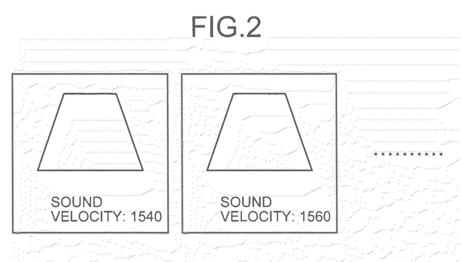
[0097]For example, as shown in FIG. 9, similarly to the first embodiment, assuming that the set sound velocity at the present moment is “1540 m / sec”, and a variable range of the set sound velocity is “from 1400 m / sec to 1600 m / sec”; when the sound-velocity switching button is pressed, the sound-velocity switching regulation unit 151a regulates switching of the set sound velocity based on that time-intervals of switching the sound velocity are regular, and value-intervals of switching the sound velocity value are constant (interval 20 m / sec in the figure).
[0098]I
third embodiment
[0124]Precisely, as shown in FIG. 11, in the ultrasound diagnosis apparatus when a request for image display is received from the operator via the input device 3 (Yes at Step S401); the monitor 2 displays ultrasound images sequentially read from the image memory 14, in cine display, by the control by the display control unit 153 (Step S402).
[0125]The image-creation control unit 152 then determines whether ultrasound image is selected as the freeze button of the input device 3 is pressed by the operator who refers to ultrasound images displayed in cine display on the monitor 2 (Step S403).
[0126]If ultrasound image is not selected (No at Step S403); the display control unit 153 controls display such that the cine display is continued on the monitor 2 (Step S404); and the image-creation control unit 152 continues determination processing at Step S403.
[0127]By contrast, if an ultrasound image is selected (Yes at Step S403); the image-creation control unit 152 controls the reception delay-
PUM
 Abstract
Description
Claims
Application Information
 - R&D Engineer
- R&D Manager
- IP Professional
- Industry Leading Data Capabilities
- Powerful AI technology
- Patent DNA Extraction
Browse by: Latest US Patents, China's latest patents, Technical Efficacy Thesaurus, Application Domain, Technology Topic.
© 2024 PatSnap. All rights reserved.Legal|Privacy policy|Modern Slavery Act Transparency Statement|Sitemap