Ultrasonograph
A diagnostic device, ultrasonic technology, applied in sonic diagnosis, infrasonic diagnosis, ultrasonic/sonic/infrasonic diagnosis, etc., can solve problems such as difficult operation, and achieve the effect of improving operability and mobility
- Summary
- Abstract
- Description
- Claims
- Application Information
AI Technical Summary
Benefits of technology
Problems solved by technology
Method used
Image

Examples
no. 1 approach
[0018] refer to Figure 1 to Figure 16 The ultrasonic diagnostic apparatus of the first embodiment will be specifically described.
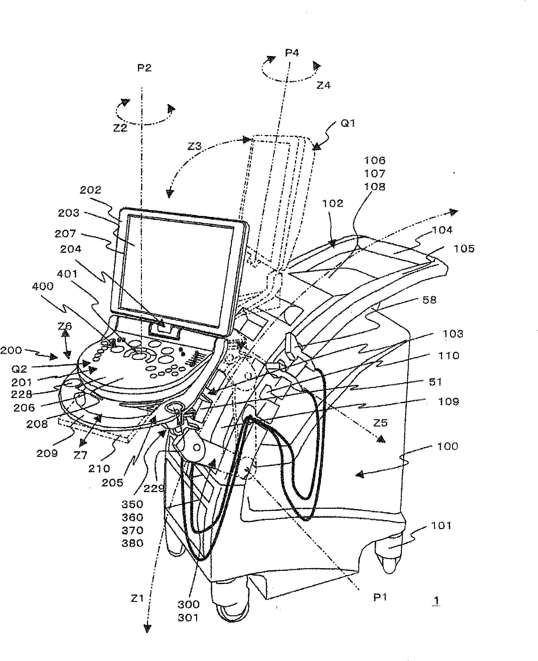
[0019] First, refer to figure 1 , the schematic configuration of the ultrasonic diagnostic apparatus according to the present embodiment will be described. figure 1 It is a perspective view showing a schematic configuration of the ultrasonic diagnostic apparatus.
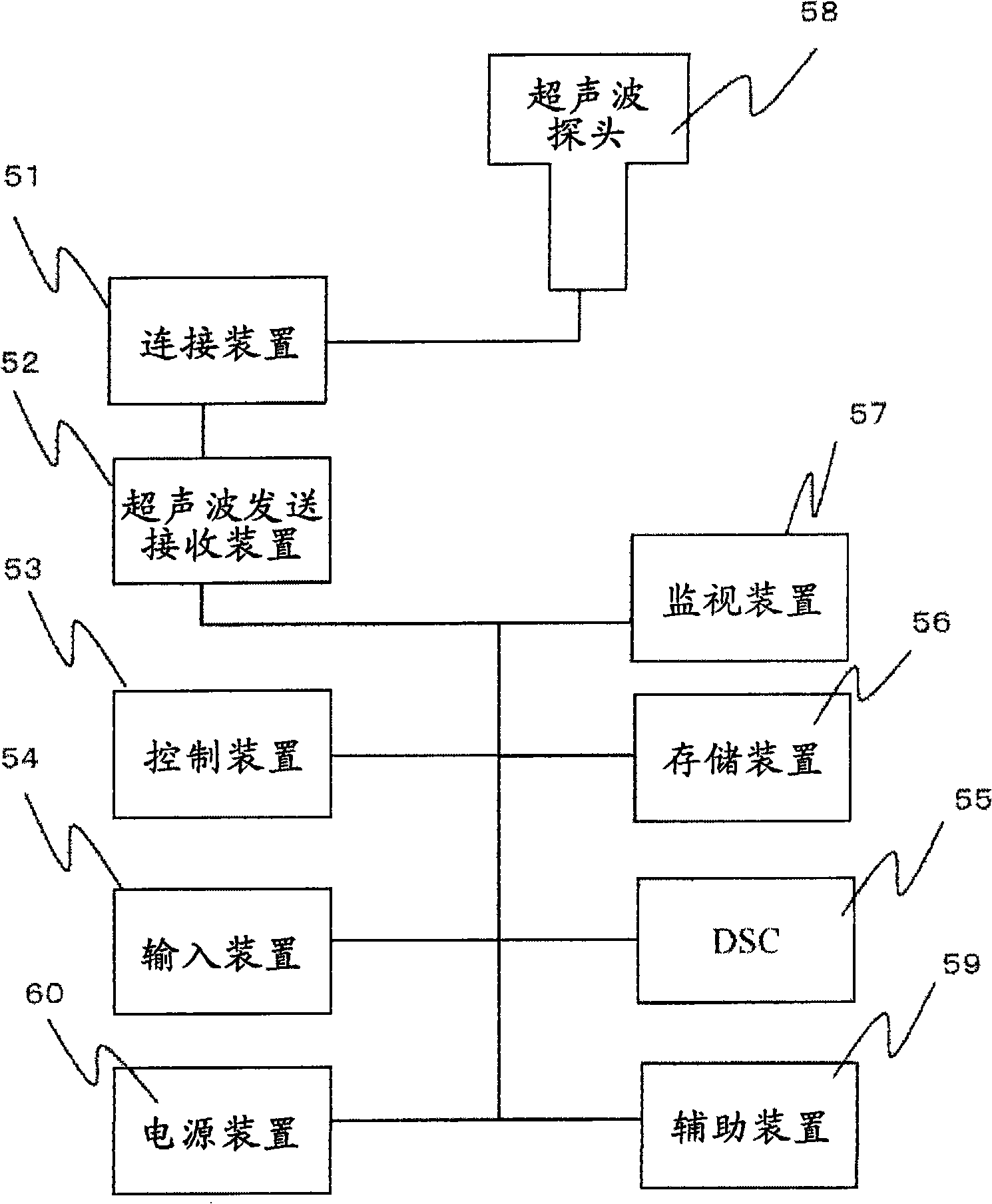
[0020] exist figure 1 In the above, the ultrasonic diagnostic apparatus generally indicated by reference numeral 1 is configured to include: a main body frame 100 provided with a rotating wheel 101; an operation device 200; a movable arm 300 connected to the above-mentioned operation device 200 movably relative to the above-mentioned main body frame 100; A plurality of ultrasound probes 58 .
[0021] The main body frame 100 is provided with the above-mentioned rotating wheels 101 at four corners of the bottom surface of a box-shaped frame, and a frame handle 102 for moving the main
no. 2 approach
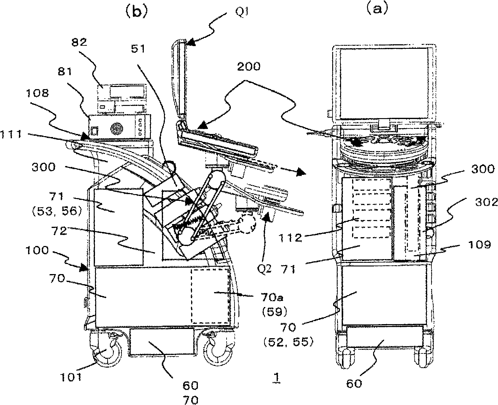
[0138] Second, refer to Figure 17 , an embodiment related to the ultrasonic diagnostic apparatus 1a of the second embodiment will be described. Figure 17 It is a schematic mechanism diagram of the elevating function mechanism accommodation part of the ultrasonic diagnostic apparatus according to the second embodiment, (a) is a plan view in the first posture Q1, (b) is a side view in the first posture Q1, and (c) is a diagram It is a plan view of the second posture Q2 and the third posture Q3, and the figure (d) is a side view of the second posture or the third posture Q3.
[0139] First, in Figure 17 In this embodiment, a rearwardly inclined device arrangement surface 103a is provided on the front surface of the main body housing 100a, and the operation device 200 is vertically raised and lowered along the inclined device arrangement surface 103a. The lifting function mechanism part 301a is composed of: a lifting part 340 provided in the main body frame 100a; a horizontal ar
Embodiment approach
[0146] In the above-mentioned embodiment, although the control unit 53 is provided in the above-mentioned main body housing 100 , it may also be provided on the operation device 200 .
[0147] In addition, as another embodiment, a configuration in which the arm moving groove 109 is covered with a corrugated cover may also be employed. For example, the upper end of the arm movement groove 109 and the movable arm 300, and the movable arm 300 and the lower end of the arm movement groove 109 are respectively provided with a cover of a stretchable corrugated structure, thereby covering the arm moving along with the movement of the arm movement groove 109. The opening of the moving groove 109 can prevent foreign matter from entering the arm moving groove 109 .
[0148] In addition, a cooling vent may be provided on the inclined surface 114 formed behind the upper surface of the main body frame 100 . In this case, the heat dissipation vents may be opened and closed by providing the abo
PUM
 Abstract
Description
Claims
Application Information
 - R&D Engineer
- R&D Manager
- IP Professional
- Industry Leading Data Capabilities
- Powerful AI technology
- Patent DNA Extraction
Browse by: Latest US Patents, China's latest patents, Technical Efficacy Thesaurus, Application Domain, Technology Topic.
© 2024 PatSnap. All rights reserved.Legal|Privacy policy|Modern Slavery Act Transparency Statement|Sitemap