Protective case for fan

Inactive Publication Date: 2011-03-03
ASIA VITAL COMPONENTSSHEN ZHEN
View PDF7 Cites 6 Cited by
  • Summary
  • Abstract
  • Description
  • Claims
  • Application Information

AI Technical Summary

Benefits of technology

[0015]By providing the first and second retaining portions, a fan packed in the protective case can be more stably held in place, and the same protective case can be conveniently used to pack differently sized fans to save the cost of manufacturing differently sized protective cases.
[0016]The protective case for fan according to a second embodiment of the present invention includes a case body, a receiving space, and at least one set of two first raised ribs. The case body has a closed bottom portion and a sidewall portion connected to and extended along a periphery of the bottom portion. The receiving space is defined between the bottom portion and the sidewall portion, and has an open top portion opposite to the closed bottom portion. The two first raised ribs are formed on the c

Problems solved by technology

However, heat produced by the chips during the operation thereof also increases with the increased number of chips.
Therefore, heat dissipation has become a very important issue in the electronic industry.
Generally, the fan is subject to invasion by dust and foreign matters in the process of transporting, handling, or selling the fan.
The invaded dust and foreign matters would inevitably move from the operating fan to different electronic elements, resulting in short circuit and burnout of the electronic elements.
It requires increased cost to manufacture differently sized protective cases, and it is troublesome for an operator to verify and select a correctly sized protective case each time a fan is to be packed.
In some worse c

Method used


Image

  • Protective case for fan
  • Protective case for fan
  • Protective case for fan

Examples


Embodiment Construction

[0032]The present invention will now be described with some preferred embodiments thereof. For the purpose of easy to understand, elements that are the same in the preferred embodiments are denoted by the same reference numerals.

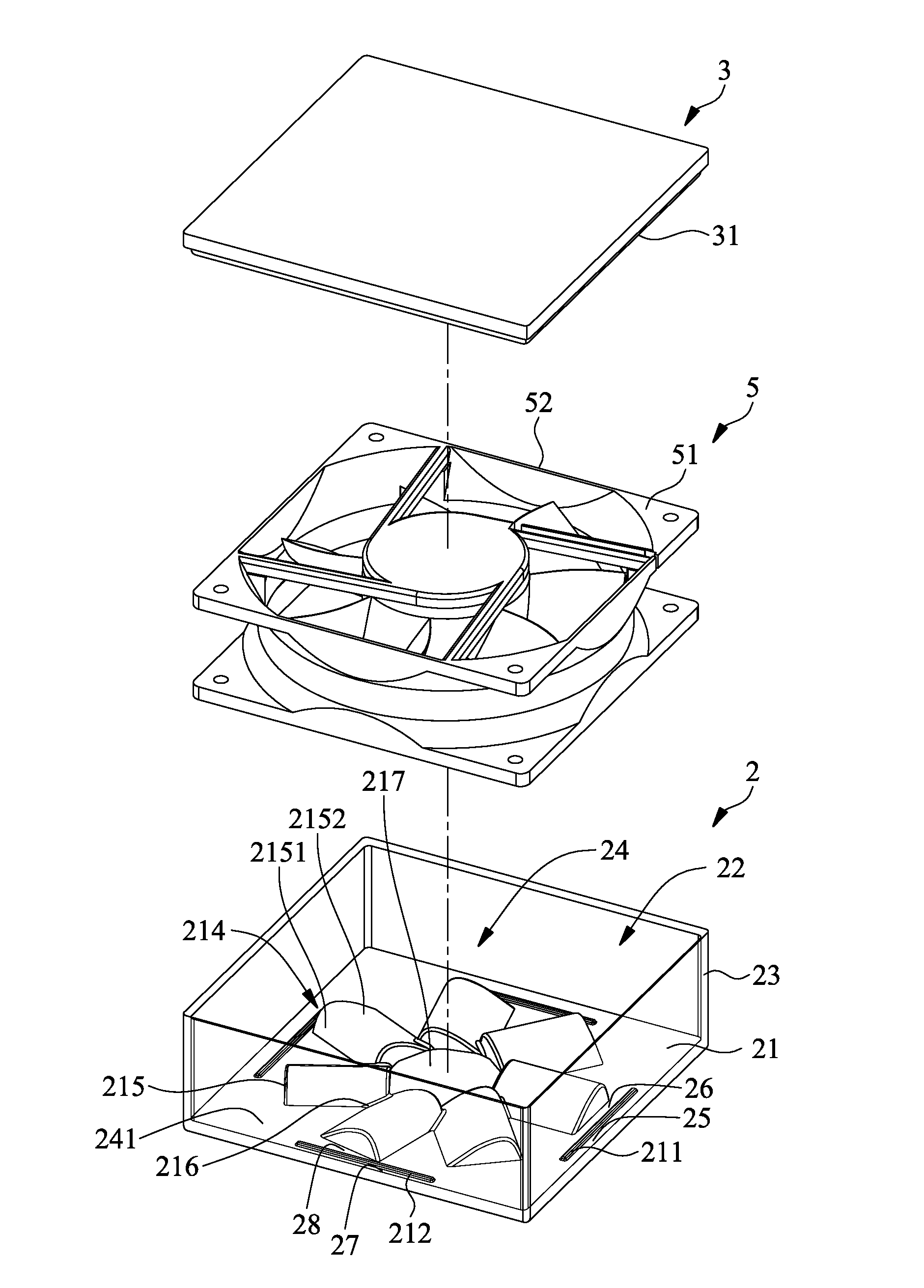
[0033]Please refer to FIGS. 2 to 4 and FIGS. 5 to 7, in which a protective case for fan according to a first preferred embodiment of the present invention applicable to packing of two differently sized fans is shown. In the illustrated first preferred embodiment, the protective case for fan of the present invention includes a case body 2 and a case cover 3. The case body 2 includes a closed bottom portion 21, an open top portion 22, and a sidewall portion 23 connected to and extended along a periphery of the bottom portion 21. The closed bottom portion 21 and the sidewall portion 23 together define a receiving space 24 therebetween for accommodating a fan 5 therein, and the case cover 3 is closed onto the open top portion 22 of the case body 2 to seal the recei


PUM


Abstract

A protective case for fan includes a case body having a closed bottom portion and a sidewall portion extended along a periphery of the bottom portion, so that a receiving space is defined between the bottom and sidewall portions. A case cover can be closed onto an open top of the receiving space to seal the same. Two first raised ribs are formed on the closed bottom portion adjacent to two opposite sides thereof, such that first retaining portions are defined between the sidewall portion and faces of the first raised ribs facing toward the sidewall portion, and second retaining portions are defined on another faces of the first raised ribs facing away from the sidewall portion. By providing the first and second retaining portions, the same protective case can be conveniently used to stably pack differently sized fans to save the manufacturing cost of the protective case.

Description


Claims


Application Information

Patent Timeline
Owner ASIA VITAL COMPONENTSSHEN ZHEN
Why Eureka
Try Eureka