Dumbbell

a dumbbell and dumbbell technology, applied in the field of dumbbells, can solve the problems of complex and sensitive, and the mechanism would be destroyed, and achieve the effect of simple and economical manufacturing

Active Publication Date: 2011-04-21
PERSONALITY GYM AB
View PDF5 Cites 30 Cited by
  • Summary
  • Abstract
  • Description
  • Claims
  • Application Information

AI Technical Summary

Benefits of technology

The technical effect of this patented inventor's new type of dumbbell has been improved safety during use compared with previous designs while still maintaining their reliability over time or at least reducing costs for production purposes.

Problems solved by technology

The technical problem addressed in this patented text relates how to improve upon existing methods for analyzing data from large amounts of time series data without sacrificing accuracy or efficiency by improving their analysis capabilities through advanced techniques such as machine learning algorithms that can learn patterns over time based on past results obtained during previous periods.

Method used


Image

  • Dumbbell
  • Dumbbell
  • Dumbbell

Examples


Embodiment Construction

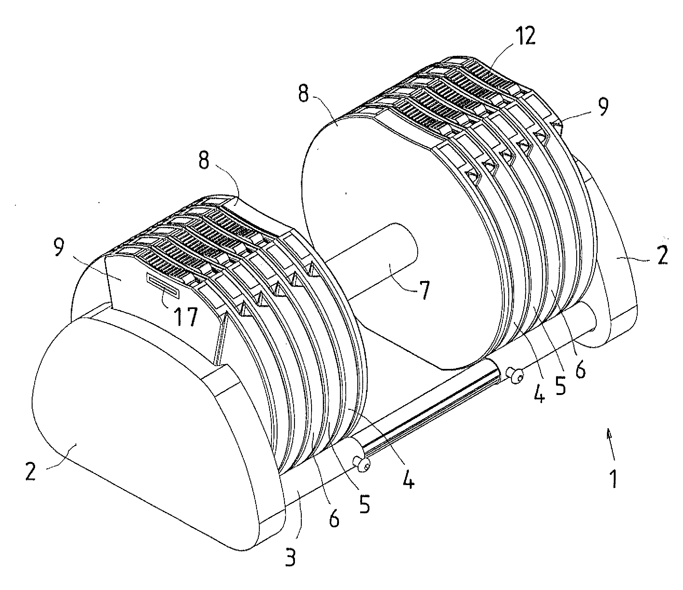
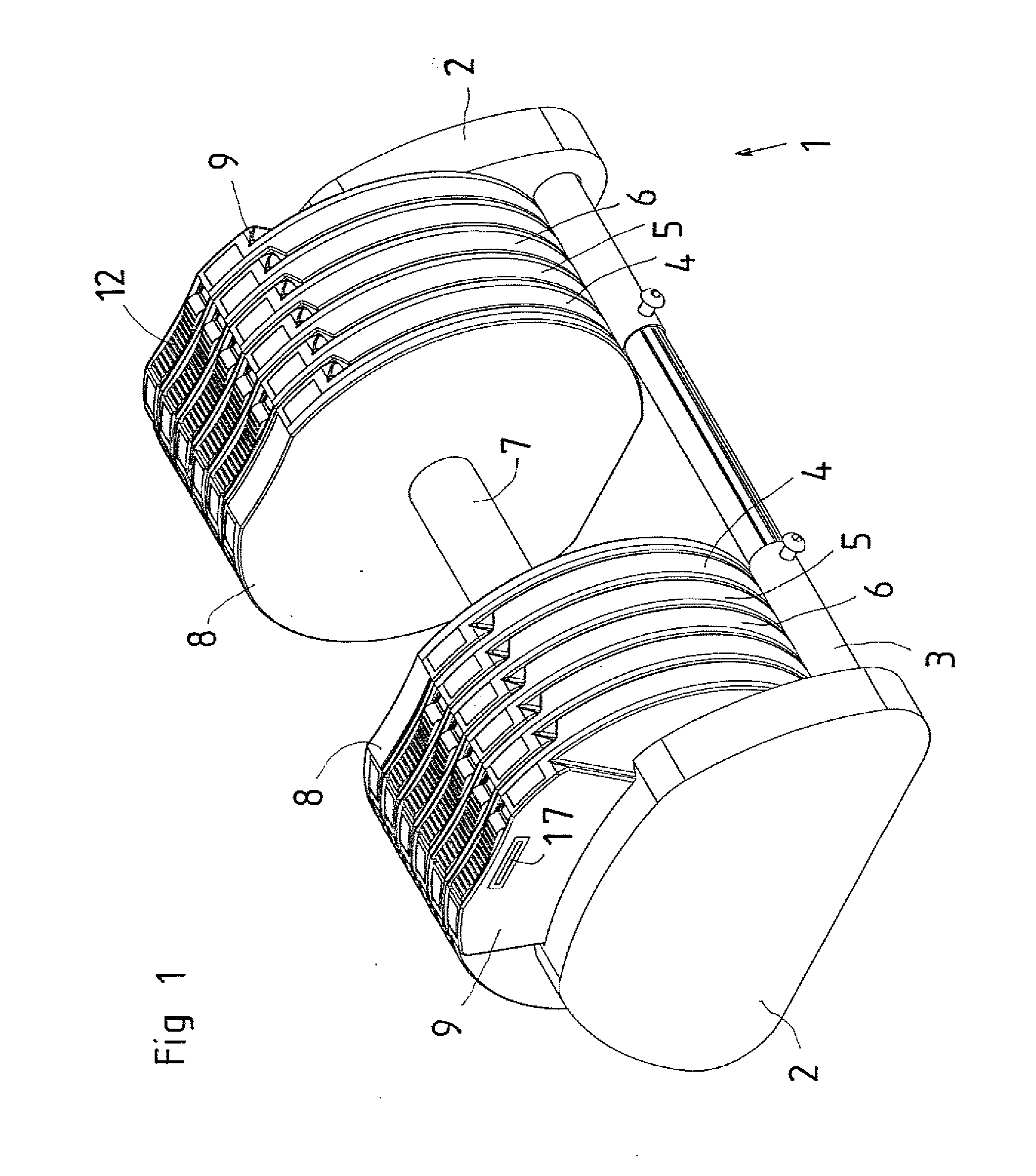
[0017]The dumbbell according to FIG. 1 is disposed in a stand 1 which, at opposing ends, has end pieces 2. The end pieces. 2 are interconnected with interconnecting portions 3 of adjustable or fixed lengths in the form of telescopic devices or fixed tubes or rods. In that case when the connecting portions 3 are of adjustable length, the stand 1 may instead be adapted in size to a specific number of weight discs 4, 5 and 6. In FIG. 1, the weight discs are shown standing upright in the stand 1 and, more precisely, resting on the two connection portions 3.

[0018]The dumbbell according to FIG. 1 further includes a handle 7 with an anchorage 8 in each end.

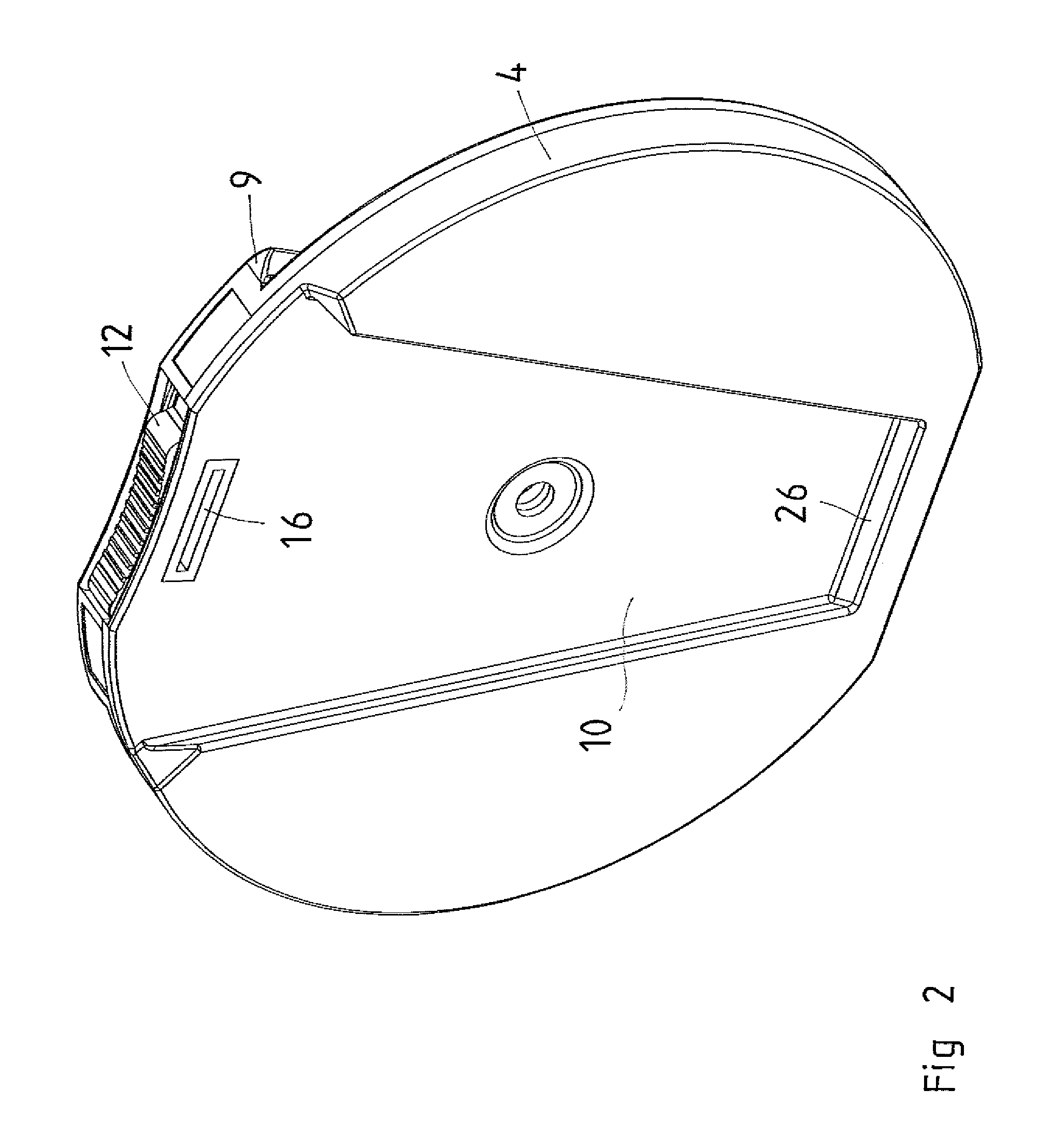
[0019]Both the anchorages 8 and the weight discs 4-6 are provided with connecting means in the form of projections 9 fitting in corresponding recesses 10 on a neighboring weight disc. The projections 9 and the recesses 10 are cuneiform and are suitably symmetric about a vertical line through the center point of the weight disc. The cross se


PUM


Abstract

A dumbbell has an optional number of weight discs which stand on end in a stand, and a handle with anchorages. The anchorages and the weight discs have connecting structures which, in the axial direction, interconnect the anchorages with a neighboring weigh disc or neighboring weight discs, respectively. On the other hand, the connecting structures permit movement transversely of the axial direction. The weight discs display locking structures, which, in the activated state in directions transversely of the axial direction, prevent mutual movements between the weight discs and the anchorages. The locking structures have locking bodies which are movable so that their directions of movement have an axial component and which are disposed at the peripheral regions of the weight discs, and also are insertable in corresponding recesses in a neighboring weight disc or an anchorage. The locking bodies are operable by an operating arrangement located inside the peripheral contour of the weight discs.

Description


Claims


Application Information

Patent Timeline
Owner PERSONALITY GYM AB
Why Eureka
Try Eureka