Electrical Power Distribution System and Method Thereof

a technology of electric power distribution system and power distribution system, which is applied in the direction of circuit arrangement, safety/protection circuit, inductance, etc., can solve the problems of limited monitoring points of electrical power distribution, electrical power not being supplied to a load, and the environment in which the plug can be received by the outl

Inactive Publication Date: 2011-05-05
EVEREADY BATTERY CO INC
View PDF9 Cites 9 Cited by
  • Summary
  • Abstract
  • Description
  • Claims
  • Application Information

AI Technical Summary

Benefits of technology

This patent describes two aspects of an electricity distribution system: attachment devices and a central controller. These attachment devices can be placed anywhere in the system and they have different functions depending on their location. One function is to provide energy for other components in the system. Another function is to help regulate or manage this energy distribution. The main benefit of these attachment devices is that they allow for more flexible placement and better management of energy sources throughout the system.

Problems solved by technology

This patents describes different technical problem addressed in this patented text: The conventional method described above cannot provide reliable connections within buildings without requiring physical contacts like electric cords or fused circuits, while also restricting their ability to monitor its own energy output based on factors like temperature and humidity levels during normal operation.

Method used


Image

  • Electrical Power Distribution System and Method Thereof
  • Electrical Power Distribution System and Method Thereof
  • Electrical Power Distribution System and Method Thereof

Examples


Embodiment Construction

Before describing in detail embodiments that are in accordance with the present invention, it should be observed that the embodiments include combinations of method steps and apparatus components related to an electrical power distribution system and method thereof. Accordingly, the apparatus components and method steps have been represented, where appropriate, by conventional symbols in the drawings, showing only those specific details that are pertinent to understanding the embodiments of the present invention so as not to obscure the disclosure with details that will be readily apparent to those of ordinary skill in the art having the benefit of the description herein. Further, like reference characters in the description and drawings represent like elements.

In this document, relational terms, such as first and second, top and bottom, and the like, may be used to distinguish one entity or action from another entity or action, without necessarily requiring or implying any actual such


PUM


Abstract

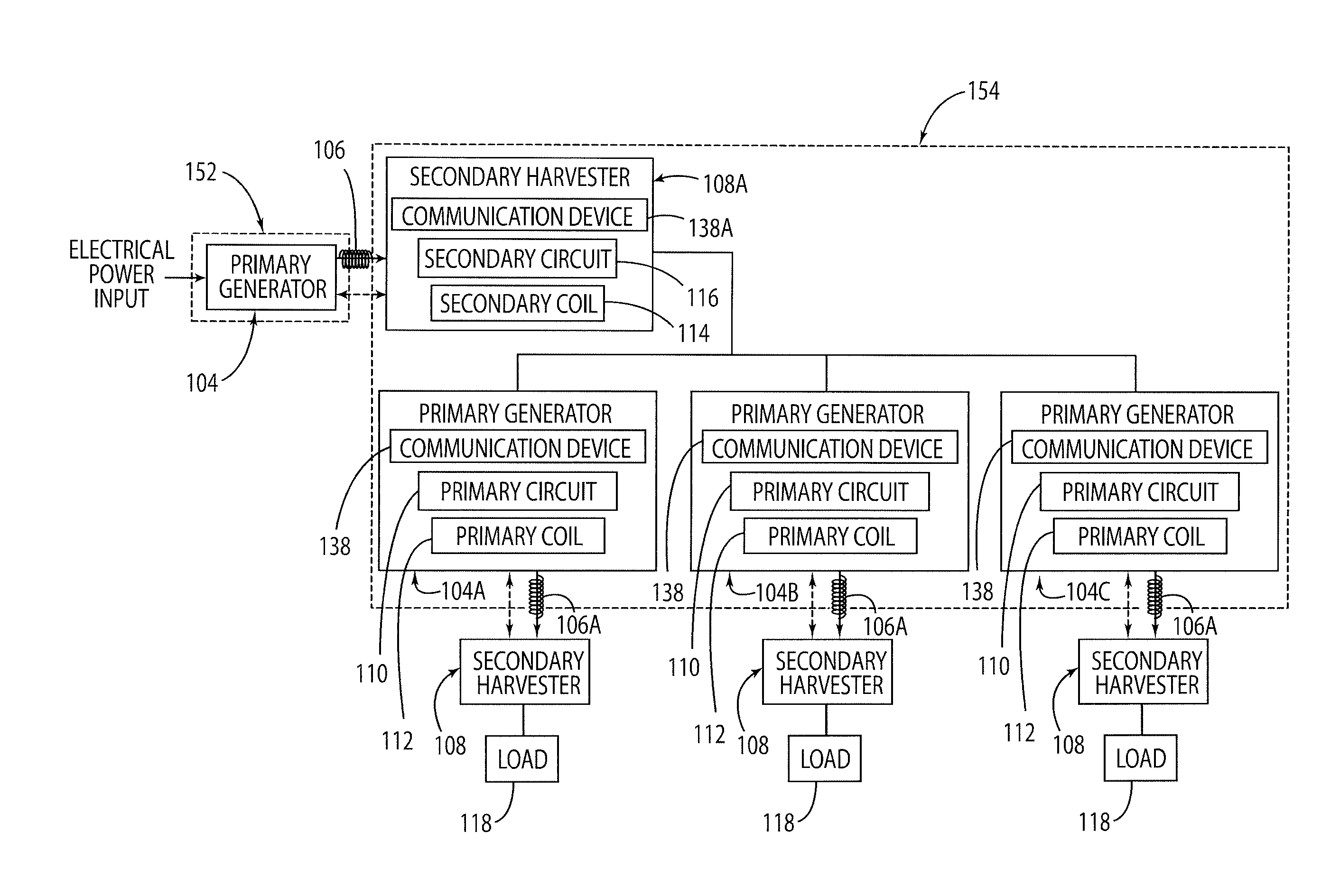
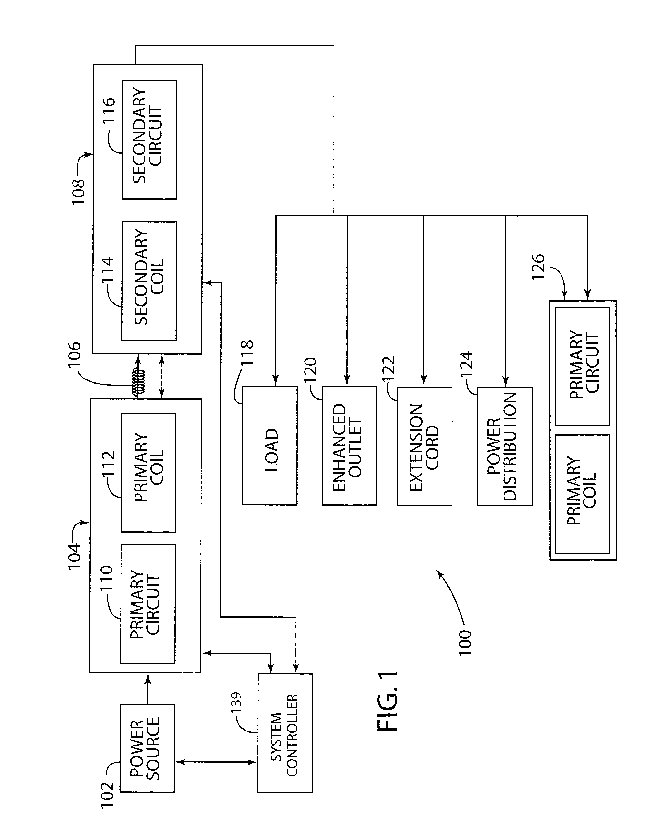
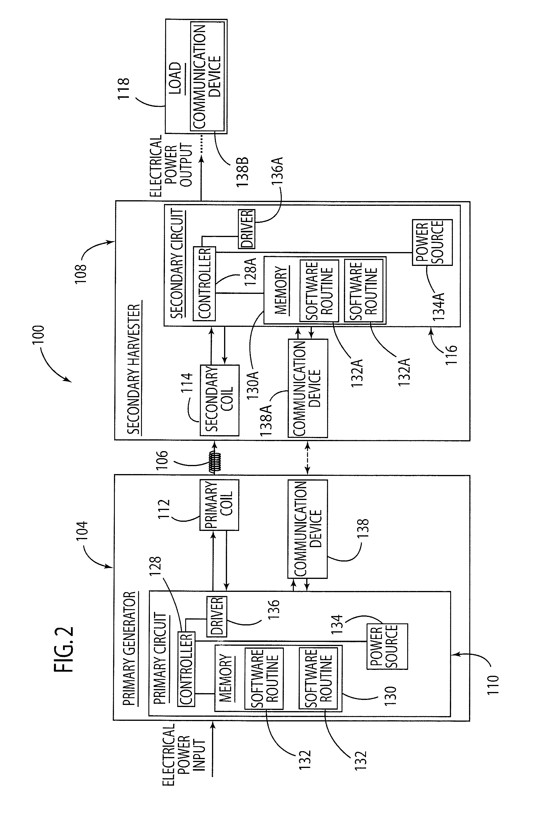
An electrical power distribution system and method are provided, wherein the system includes a primary generator and a secondary harvester. The primary generator includes a primary coil configured to emit an electromagnetic field when an electrical power is supplied to the primary coil, and a first communication device configured to communicate a signal. The secondary harvester includes a secondary coil configured to supply an electrical power when receiving the emitted electromagnetic field, and a second communication device configured to communicate the signal, such that the first and second communication devices communicate the signal independent from the emitted electromagnetic field.

Description


Claims


Application Information

Patent Timeline
Owner EVEREADY BATTERY CO INC
Why Eureka
Try Eureka