Breast implants having drug-eluting reservoirs and methods therefor

Active Publication Date: 2011-06-30
MENTOR WORLDWIDE
View PDF4 Cites 34 Cited by
  • Summary
  • Abstract
  • Description
  • Claims
  • Application Information

AI Technical Summary

Benefits of technology

[0019]These and other preferred embodiments of the pre

Problems solved by technology

The creases often appear on the anterior face of the prosthesis, which can be aesthetically undesirable as the creases can sometimes be discerned through the overlying skin of the patient.
After implantation, breast implants are subject to complications from infection.
Thus, once the infection takes hold, conventional concentrations of systemic antibiotics cann

Method used


Image

  • Breast implants having drug-eluting reservoirs and methods therefor
  • Breast implants having drug-eluting reservoirs and methods therefor
  • Breast implants having drug-eluting reservoirs and methods therefor

Examples


Embodiment Construction

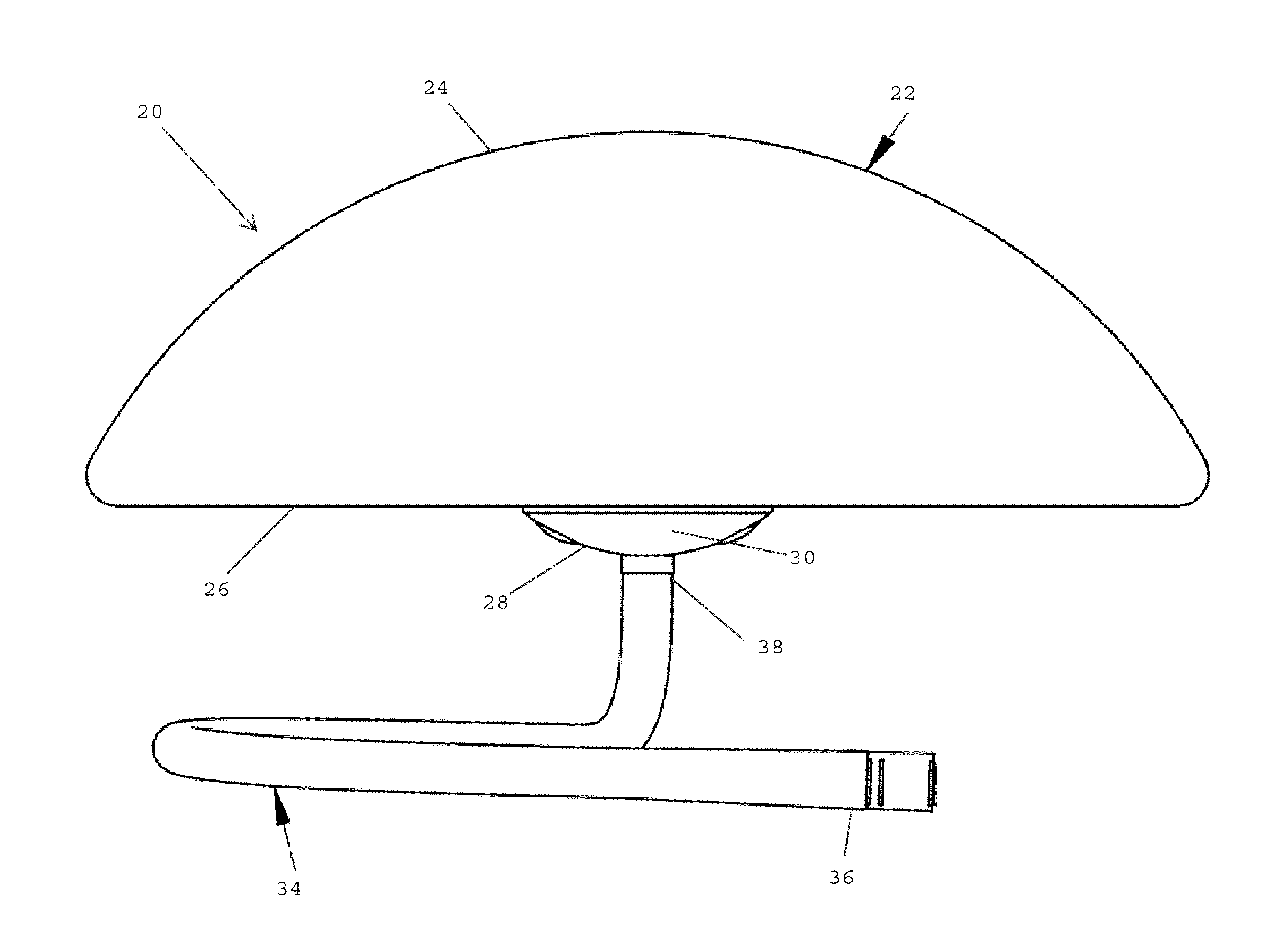
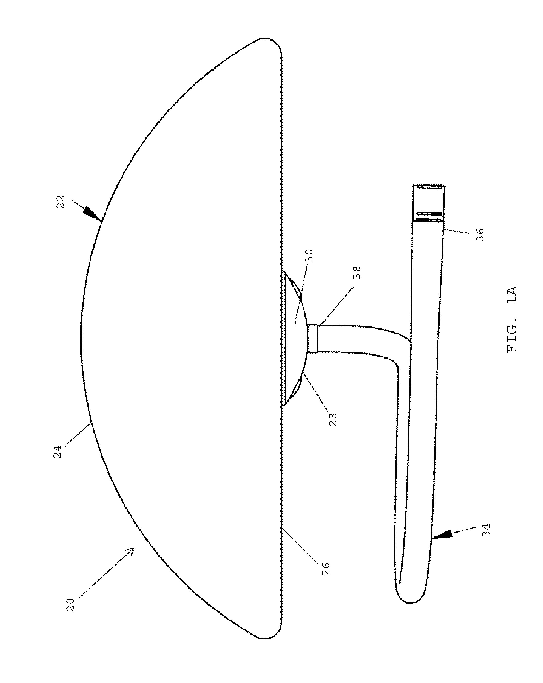
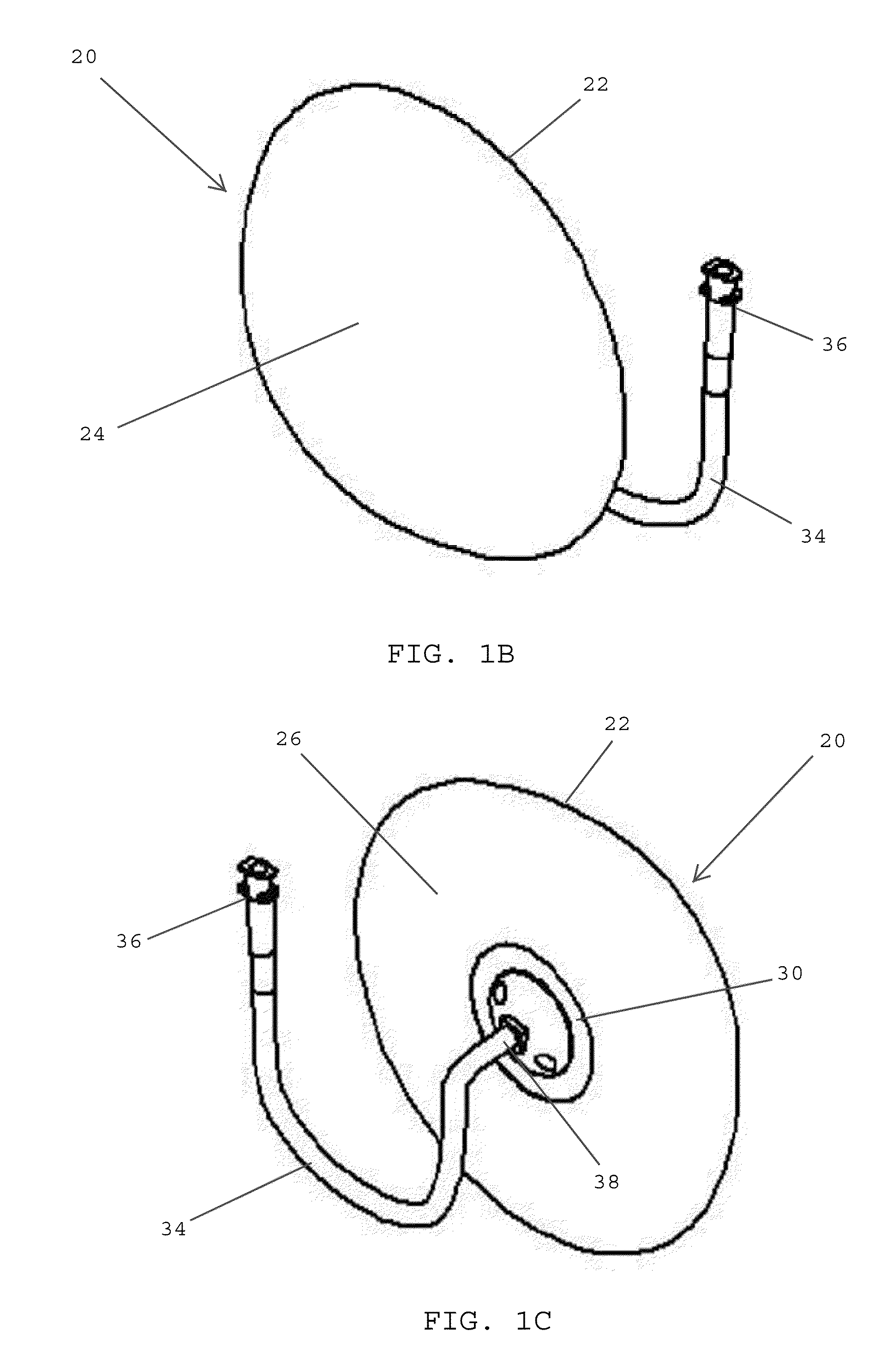
[0035]Referring to FIGS. 1A-1C, in one embodiment, a breast implant 20 preferably includes an implant shell 22, such as a silicone shell, that defines an outer surface of the implant. The implant shell is preferably adapted for being implanted within a pocket formed in breast tissue. The implant shell 22 described has an anterior face 24 and a posterior face 26. In one embodiment, the implant shell 22 is desirably formed using a mandrel. As such, the implant shell 22 may include a mandrel hole (not shown) that extends through the outer wall of the shell, and which may be used for removing the implant shell 22 from the mandrel after the shell has been formed thereon. In one embodiment, the mandrel hole preferably extends through a posterior face 26 of the implant shell 22. In other embodiments, however, the mandrel hole may be formed on an anterior face of the implant shell. In one embodiment, the mandrel hole may be used for introducing a solution, such as saline solution, a gel, or a


PUM


Abstract

A breast implant includes an implant shell having an outer surface and defining a first fluid reservoir, and a porous membrane overlying the outer surface of the implant shell and defining a second fluid reservoir. The breast implant includes a filling tube having a first conduit in communication with the first reservoir and a second conduit in communication with the second reservoir. The breast implant includes an injection dome coupled with the filling tube and having a first fluid chamber in communication with the first conduit and a second fluid chamber in communication with the second conduit. The injection dome includes an upper end having an injection cover, a lower end including a support base, the first fluid chamber located adjacent the injection cover, the second fluid chamber located adjacent the support base, and a diaphragm dividing the first and second fluid chambers from one another.

Description


Claims


Application Information

Patent Timeline
Owner MENTOR WORLDWIDE
Why Eureka
Try Eureka