Washing Appliance

a technology for washing machines and washing drums, applied in washing machines, other washing machines, textiles and papermaking, etc., can solve the problems of requiring a significant amount of energy, waste of water in the process, and limited usable capacity of such drums, so as to increase the overall size of the appliance and increase the capacity

Inactive Publication Date: 2011-07-14
REASON ANDREW +2
View PDF26 Cites 0 Cited by
  • Summary
  • Abstract
  • Description
  • Claims
  • Application Information

AI Technical Summary

Benefits of technology

The technical effect of this patented invention is that it allows for more space inside the washer drum while still being able to handle larger loads effectively.

Problems solved by technology

The technical problem addressed in this patent is how to efficiently provide both washing and launderering services while minimizing energy consumption and improving efficiency. Current methods involve using separate drums and motors for each purpose, leading to complexity and cost issues. There is a need for a simpler and less expensive solution to these challenges.

Method used


Image

  • Washing Appliance
  • Washing Appliance
  • Washing Appliance

Examples


Embodiment Construction

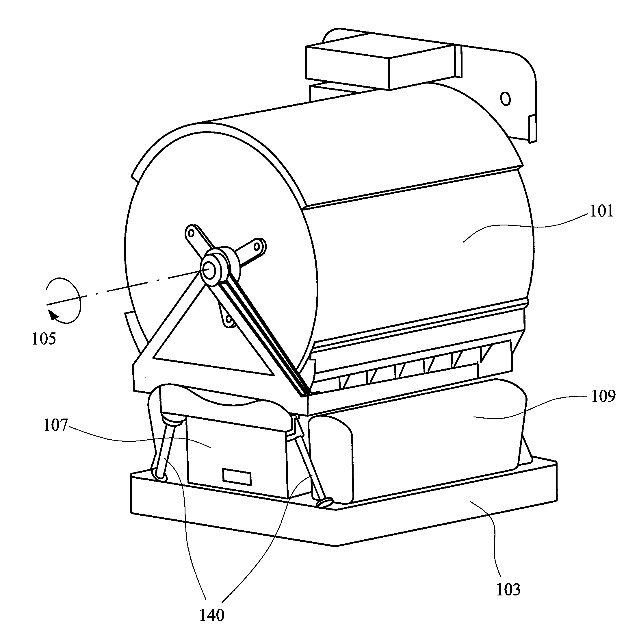
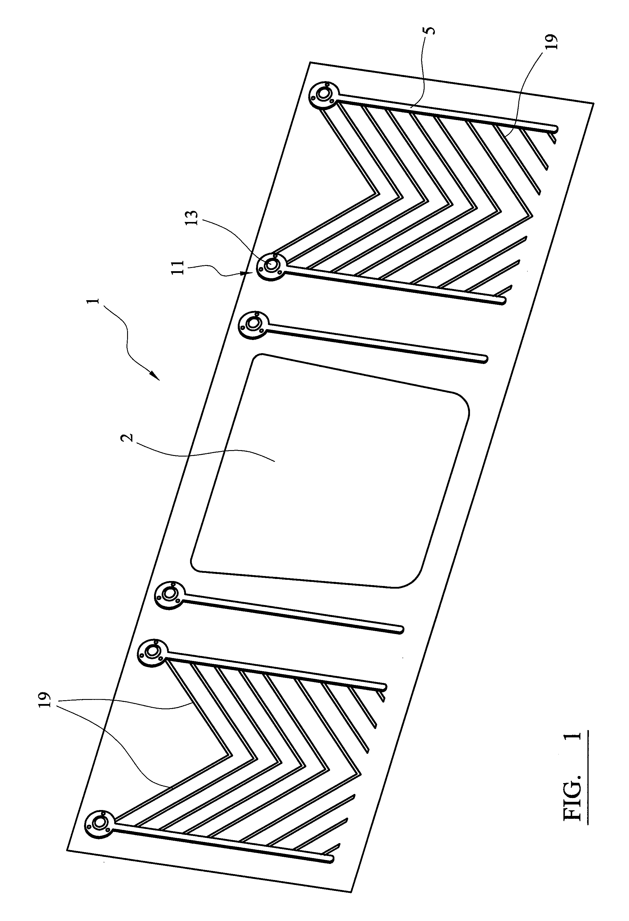
[0092]Referring to FIG. 1 of the accompanying drawings, a drum 1 according to an exemplary embodiment of the invention is formed of an elongate rectangular piece of metal, which is bent round and the ends joined together to form an open cylinder. There is a suitably sized, possibly, but not necessarily, substantially rectangular aperture 2 located approximately centrally in terms of the length and width of the metal piece forming the drum 1, that provides an opening for placing laundry into and removing laundry from, the drum 1 when assembled 3. A plurality of elongate drain channels 5 are provided in the piece of metal 1, which channels 5 run laterally across the piece of metal.

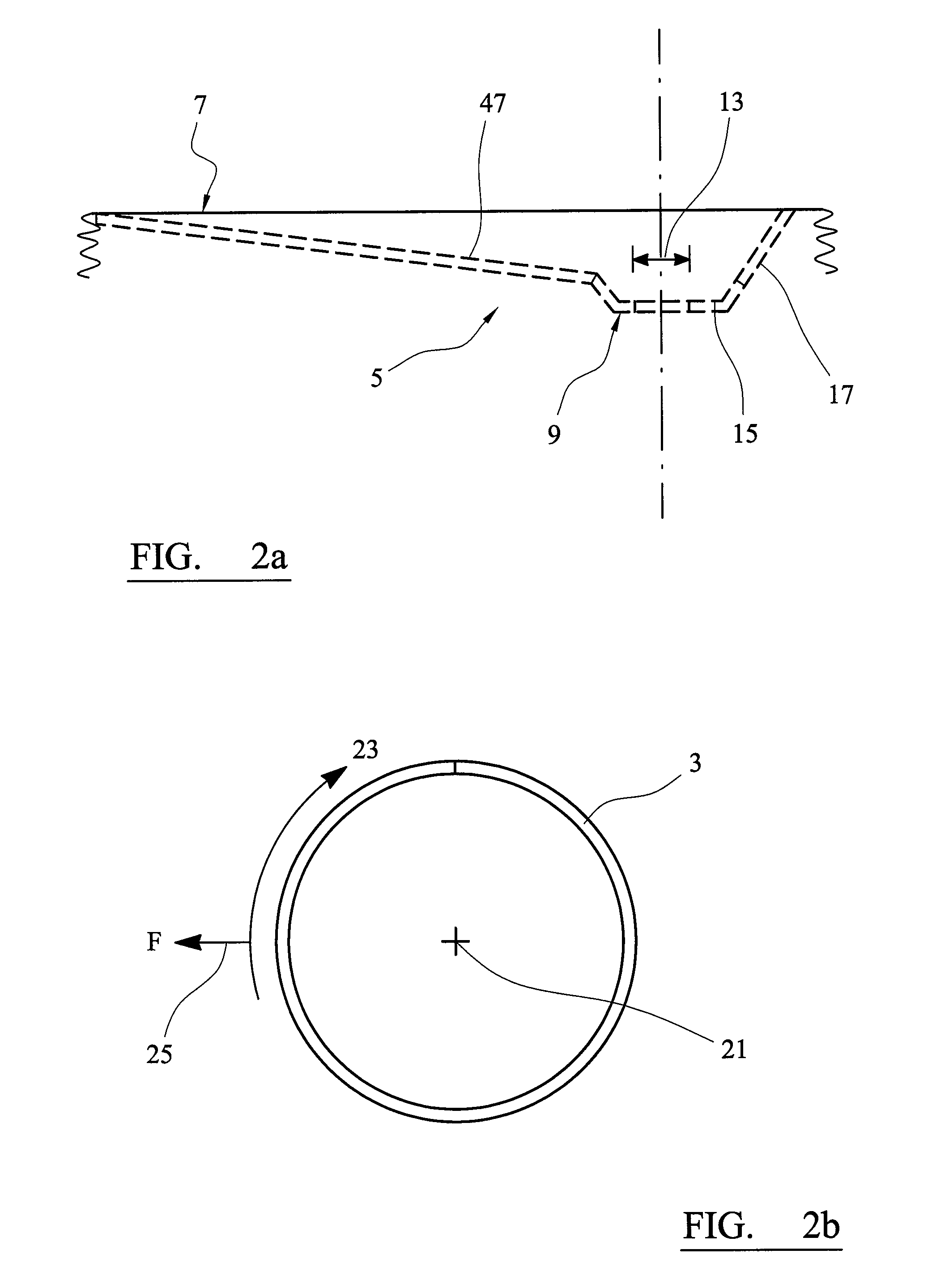
[0093]Referring to FIG. 2a of the drawings, the drain channels 5, when viewed cross-sectionally all slope in the same direction from a shallow start point 7 to a distal deep end point 9. Each deep end point 9 defines a valve housing 8 comprising a circular purging aperture 13 located centrally in an offset circ


PUM


Abstract

A washing machine or other laundry appliance has a drum that rotates during washing cycles of the appliance. The appliance further incorporates a ballast system including a reservoir having means for permitting water to flow between said reservoir and the drum, an inlet for enabling said reservoir to be filled with water, and an outlet for enabling water to be drained from said reservoir. The appliance further incorporates means for filling said reservoir and maintaining said reservoir substantially full of water during the washing cycles. Weight of the reservoir when it is substantially full of water acts to counter balance vibrations generated by the rotation of the drum during the washing cycles of the appliance.

Description


Claims


Application Information

Patent Timeline
Owner REASON ANDREW
Why Eureka
Try Eureka