Arcuate-winged solar canopy assembly

Active Publication Date: 2011-08-25
RICHARDSON DONALD S
View PDF16 Cites 19 Cited by
  • Summary
  • Abstract
  • Description
  • Claims
  • Application Information

AI Technical Summary

Benefits of technology

[0006]The invention is an assembly of elements to collect solar energy and rain water. Solar energy is converted to electricity by either photovoltaic film or laminate panels or sheets mounted atop arcuate, curved canopy structures that are formed and positioned like “wings”. Rainwater is collected by the low-incidence curved wings and directed to a central trough along the wings' structural spine, which conducts it through a support column to a water container or vessel. In a preferred embodiment the vessel is an underground container extending parallel to and as long as the above-ground structural spine of the assembly. The low-incidence curved wings allow for optimal solar collection (i.e., power production) in mid-day during summer months in the northern latitudes when utilities often experience their highest daily and historic demand. The principal application is for parking lots, as the full canopy assembly provides site and vehicle cooling, and mitigates against albedo effect for additional environmental benefits. The invention can be used to collect solar energy, and water from rain or snowmelt. In addition to parking lots, it can be installed in parks, marinas, walkways, remote areas, and urban areas with adequate solar access to provide electricity and store water for later distribution. It further provides a non-polluting, zero carbon emission method of supplying electricity, and the ability to charge or re-charge electric vehicles or equipment without additional fuel expenditure or supplemental connection to an existing electrical grid. In it's parking lot application, it provides shade for vehicles, thereby reducing the need for drivers to run their air conditioning systems to pre-cool their vehicles prior to driving. In its farm application, it collects water for redistribution, provides electricity to pumps and other farm equipment and provides shelter for crop, feed, animals and equipment storage. In it's marine application, it may be erected on a pier and provide grey water for cleaning watercraft, power for recharging boat batteries and sunshade for pier users and craft. The arcuate curvature in the winged solar canopy assembly of the invention creates a “waterfall effect”, such that water moving toward the trough at the proximal edges of the canopy increases in speed due to the curvature and pulls the water at the distal edges of the canopy along with it. This causes the water on the distal edges of the canopy to move faster than water falling on a non-curved canopy. This “sweeping” of the canopy by rainfall assists in the cleaning of the assembly. In addition, the structure and shape of the canopy wing arms allow the edges to vibrate in the wind, which also facilitates the movement of water, snow and debris off the canopy.

Problems solved by technology

Solar panels placed atop free standing structures combine power generation with, for example, shade production, which results in the maximization of the value and use of the airspace.
Certain problems are associated with the foregoing approaches.
This makes them not readily accessible, often compromises roof integrity and results in a rigid and expensive assembly.
In addition, conventional roof top solar arrays are typically designed and disposed along a single slope plane, which may not be ideal in some locales, and are problematic for example where there is snow or ice buildup in the winter.
Inclined, fixed plane canopies with mono-planar wings cannot maximize solar collection capability without adjustment to the wing angle.

Method used


Image

  • Arcuate-winged solar canopy assembly
  • Arcuate-winged solar canopy assembly
  • Arcuate-winged solar canopy assembly

Examples


Example

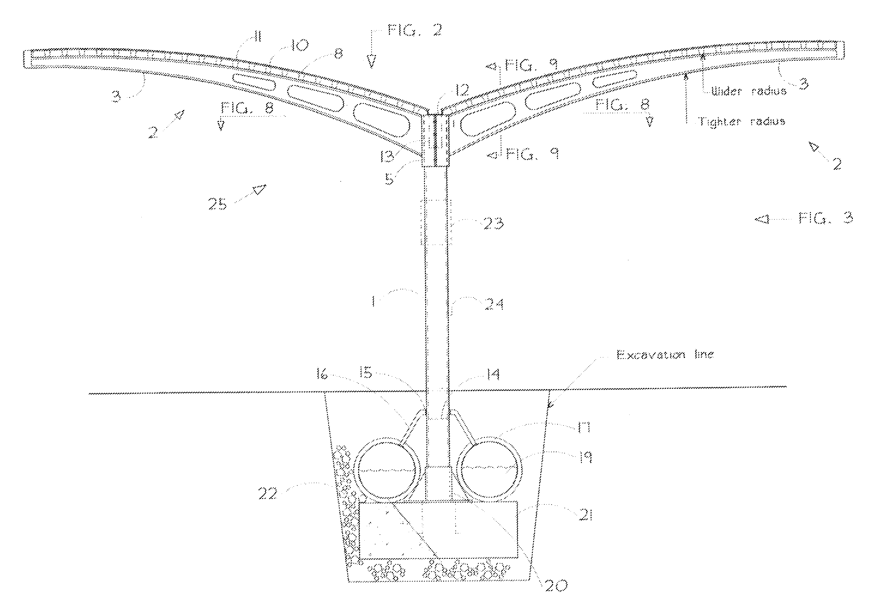
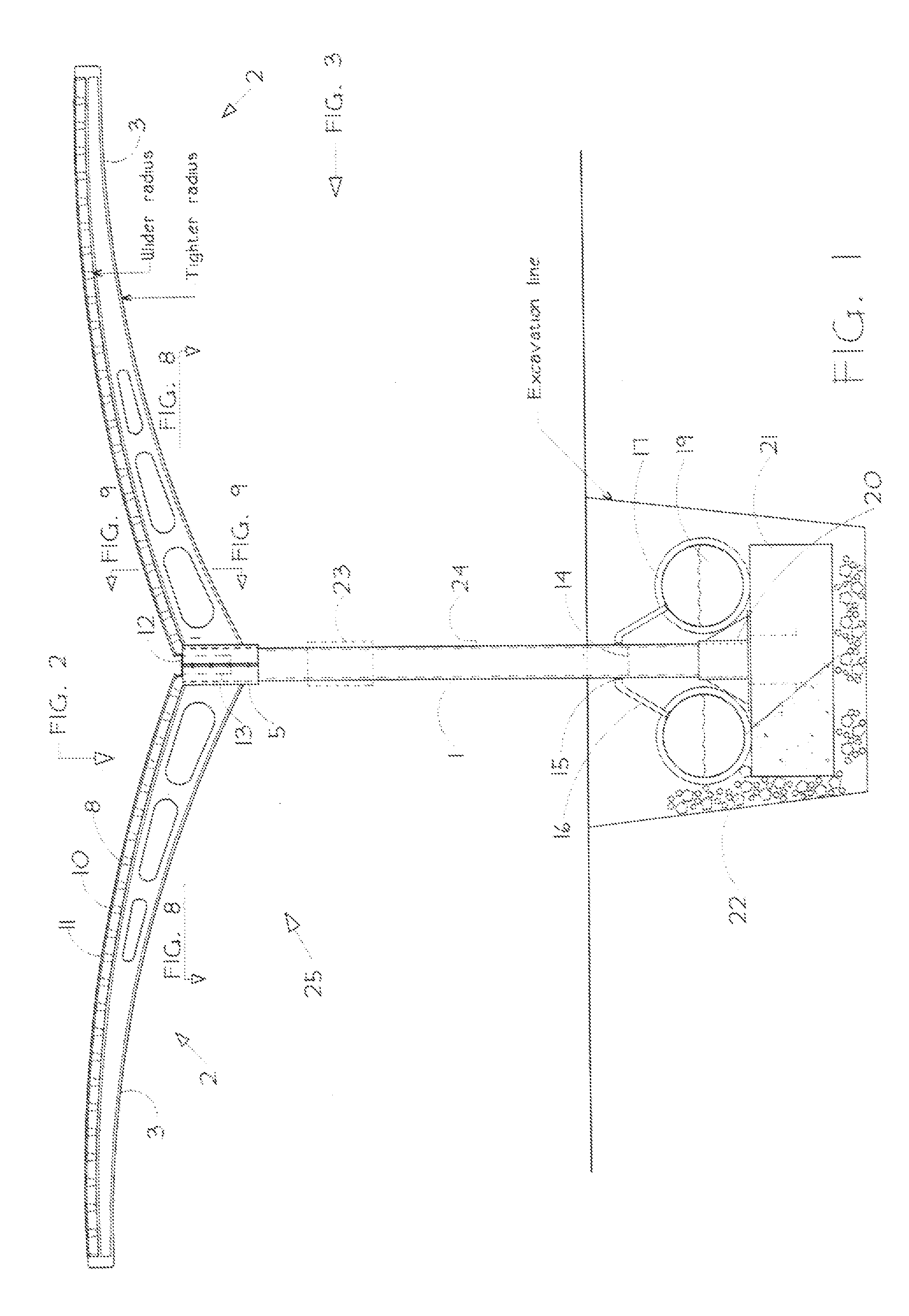
[0042]FIG. 5 illustrates a second embodiment of the wing structural arm of the assembly in which the plurality of paired, space-apart wing structural arms are eliminated and replaced by a pair of continuous wings that extend longitudinally along the entire canopy structure. The continuous arcuate wings, 40, of this embodiment have an upper panel 43 and a lower panel 44 and are hollow except for one or more fixed braces or spars, 41, extending between the upper panel of the wings and the lower panel of the wings. Like the first embodiment, hollow continuous wings 40 are formed with a low-incident, arcuate, downwardly-sloping curve and are positioned with one end proximal to support column 1 and the other end distal to the support column. Also like the first embodiment, the continuous arcuate wings have proximal ends 45 and distal ends 46 and the proximal ends and are arranged to be in opposed relation to each other forming a structural spine in the assembly. The arcuate curvature in the


PUM

PropertyMeasurementUnit
Weightaaaaaaaaaa
Poweraaaaaaaaaa
Weight ratioaaaaaaaaaa

Abstract

The invention is an assembly of elements to collect solar energy and rain water. Solar energy is converted to electricity by either photovoltaic film or laminate panels or sheets mounted atop arcuate, curved canopy structures that are formed and positioned like “wings”. Rainwater is collected by the low-incidence arcuate curved wings and directed to a central trough along the wings' structural spine, which conducts it through a support column to a water container or vessel. In a preferred embodiment the vessel is an underground container extending parallel to and as long as the above-ground structural spine of the assembly.

Description


Claims


Application Information

Patent Timeline
Owner RICHARDSON DONALD S
Why Eureka
Try Eureka