Electrical switchgear

a switchgear and electric technology, applied in the direction of air-break switch, switchgear with a retractable carriage, contact, etc., can solve the problem of compact switch arrangement, and achieve the effect of facilitating access to the switchgear

Active Publication Date: 2012-01-12
EATON INTELLIGENT POWER LIMITED
View PDF3 Cites 5 Cited by
  • Summary
  • Abstract
  • Description
  • Claims
  • Application Information

AI Technical Summary

Benefits of technology

The invention allows for more space-saving storage by making it easier to arrange certain parts within an enclosed area that can easily connect with other equipment or devices located behind them. This makes accessing these areas even faster and simpler compared to traditional arrangements where all connections are at one end.

Problems solved by technology

The technical problem addressed in this patented text relates to improving upon existing designs where many parts have been added but they were difficult to remove due to their size and complexity. This makes maintaining these systems more challenging because there may only be limited resources available when needed.

Method used


Image

  • Electrical switchgear
  • Electrical switchgear
  • Electrical switchgear

Examples


Embodiment Construction

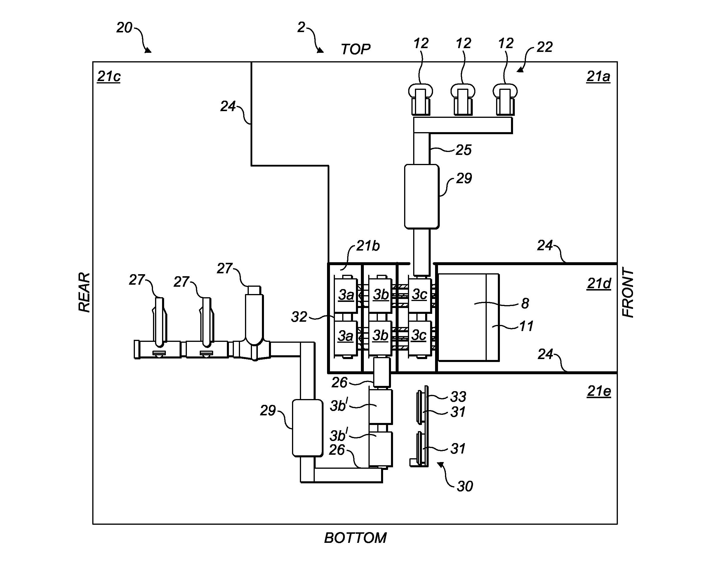
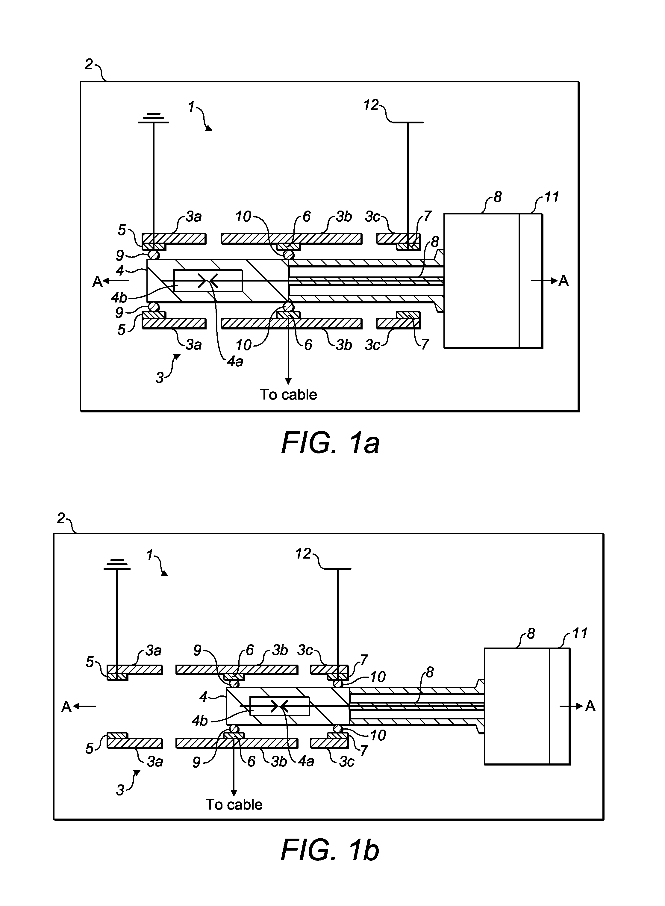
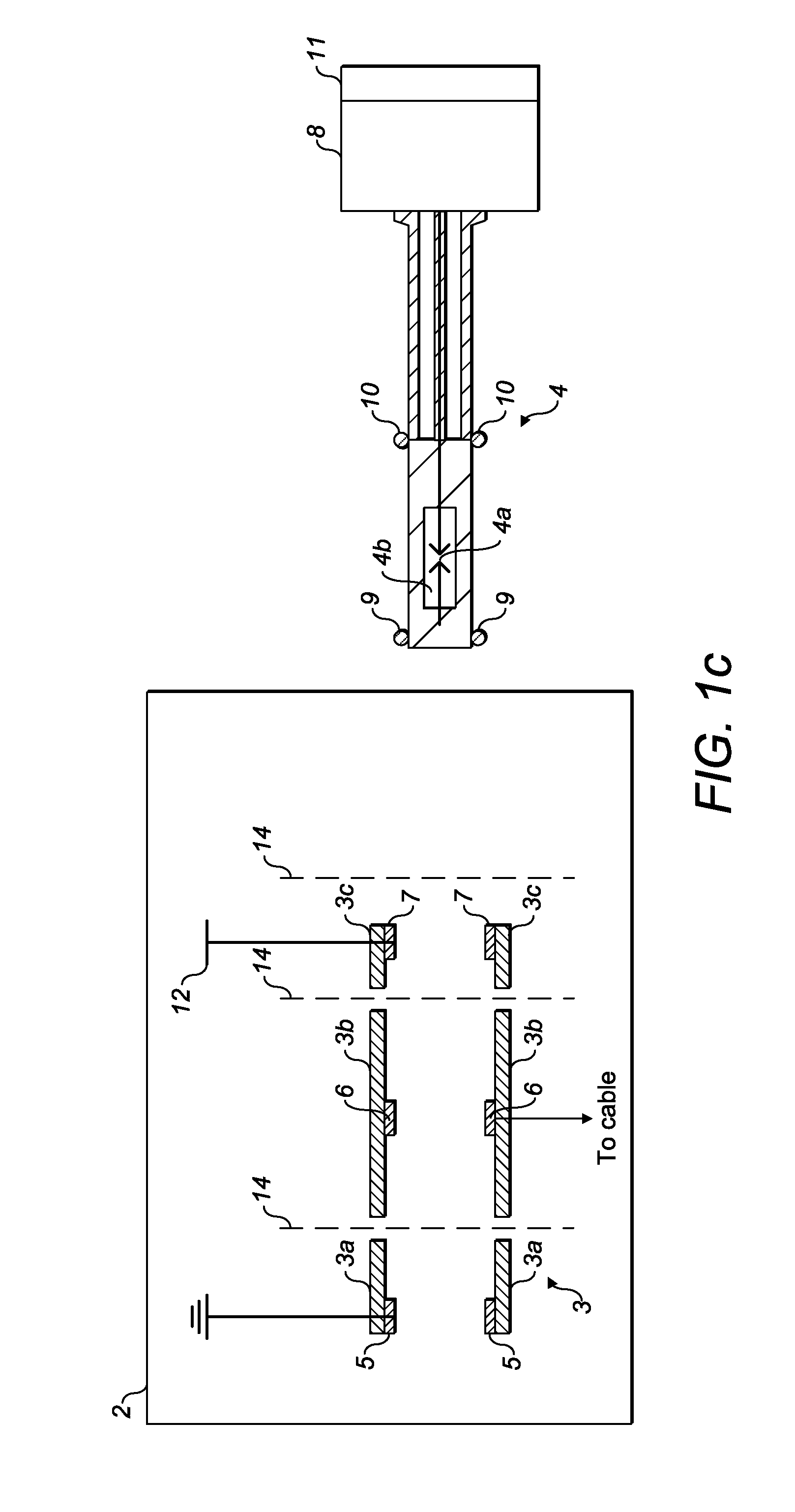
[0023]Referring to FIGS. 1a to 1c, a switch arrangement 1 for an electrical switchgear 2 comprises an electrical pole or terminal 3 and a switching device 4, for example, a circuit breaker switching element. The terminal 3, is fixed within the switchgear 2 and comprises a housing made up of first 3a, second 3b and third 3c electrically insulating tubular sections of substantially equal internal diameter which are spaced apart lengthwise along a common longitudinal axis A. The three tubular sections may for example be formed of an epoxy resin material. Each of the three tubular sections 3a, 3b and 3c has a respective electrical contact 5, 6, 7 located inside of it. The first section 3a has an earth contact 5 that is electrically connectable to earth. The second section 3b has a cable contact 6 in electrical connection with a cable (not shown) of the switchgear 2 and hence to a load (not shown) and the third section 3c comprises a bus bar contact 7 in electrical connection with an electr


PUM


Abstract

An electrical switchgear comprises a front, a back and a switch arrangement. The switch arrangement comprises a terminal arrangement comprising an electrical contact for a bus and an electrical contact for a load connection which are spaced apart along an axial direction; and a device that is driveable into said terminal arrangement to a service position to make an electrical connection between said electrical contact for said load connection and said electrical connection for said bus. The electrical contact for said load connection is located closer to said back of said switchgear than is said electrical contact for said bus.

Description


Claims


Application Information

Patent Timeline
Owner EATON INTELLIGENT POWER LIMITED
Why Eureka
Try Eureka