Loop scavenged two-stroke internal combustion engine

a two-stroke, internal combustion engine technology, applied in combustion engines, machines/engines, mechanical equipment, etc., can solve the problems of low fuel efficiency, increased cost, and insufficient aforesaid blow-by-restraining

Active Publication Date: 2012-02-02
YAMABIKO CORP
View PDF1 Cites 1 Cited by
  • Summary
  • Abstract
  • Description
  • Claims
  • Application Information

AI Technical Summary

Benefits of technology

The present invention relates to an improved design for a two-cycle engine that reduces blow-by during its scavenge process. By making certain parts of the scavenging passage have different inclinations, it prevents the flow velocity of the scavenging gases from being too fast when they hit the walls near the openings of the exhaust ports. This helps prevent damage caused by excessive pressure buildup and improves efficiency.

Problems solved by technology

The technical problem addressed in this patent is finding ways to improve the design of scavengers in engines that use two-stroke cycles or similar methods to reduce emissions during their workday.

Method used


Image

  • Loop scavenged two-stroke internal combustion engine
  • Loop scavenged two-stroke internal combustion engine
  • Loop scavenged two-stroke internal combustion engine

Examples


Embodiment Construction

[0019]Hereinafter, an embodiment of the present invention will be described with reference to the drawings.

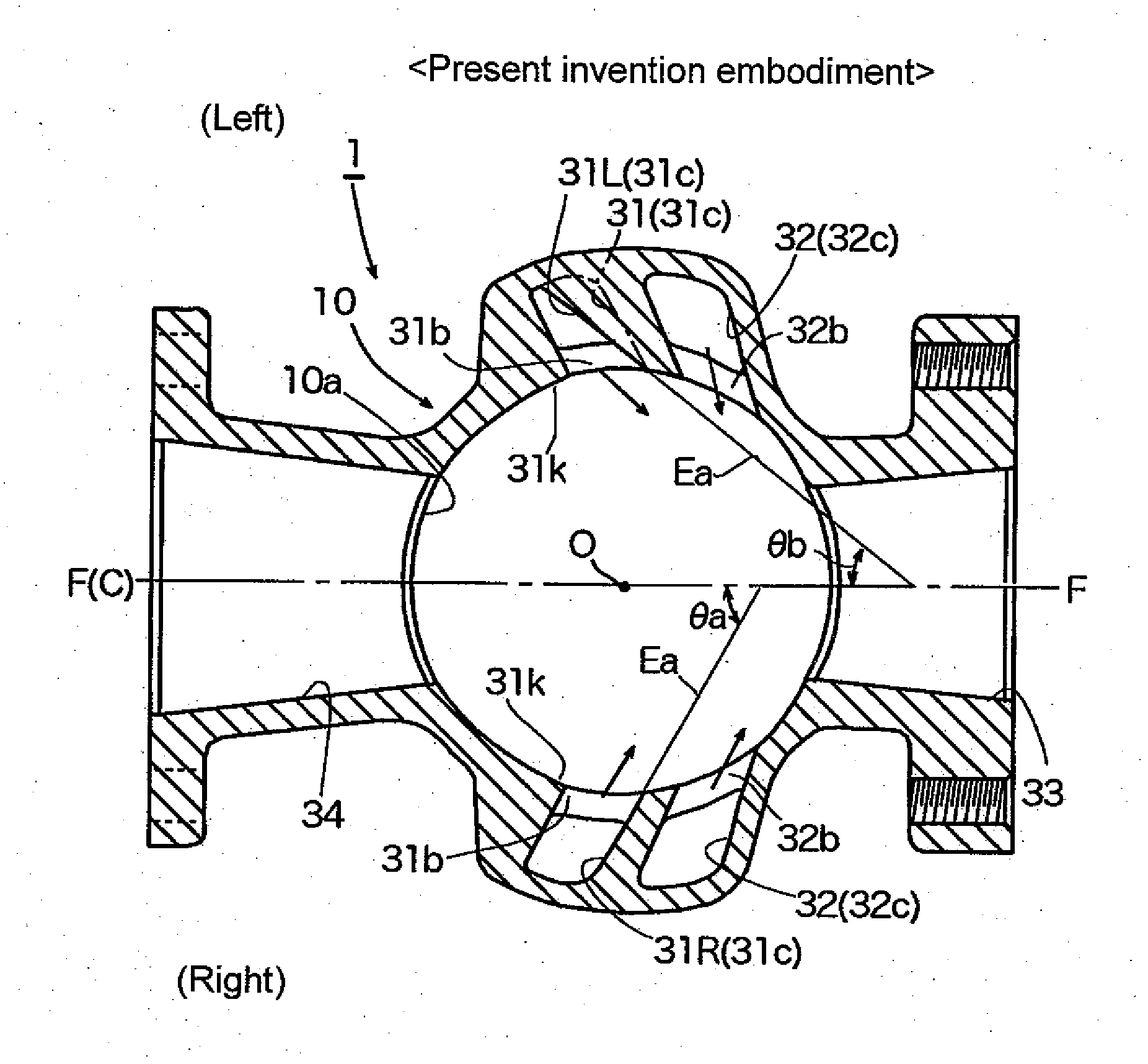
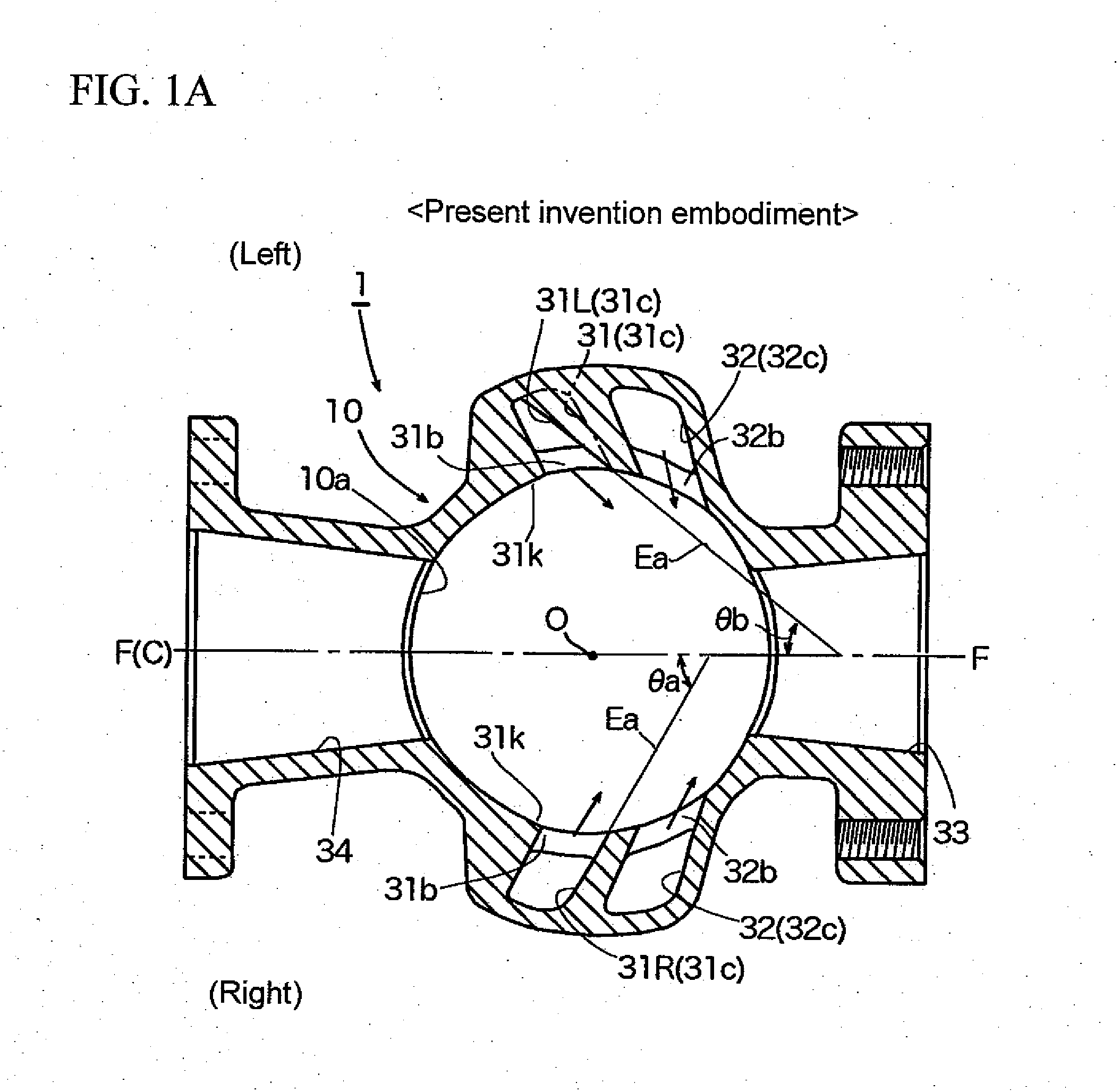
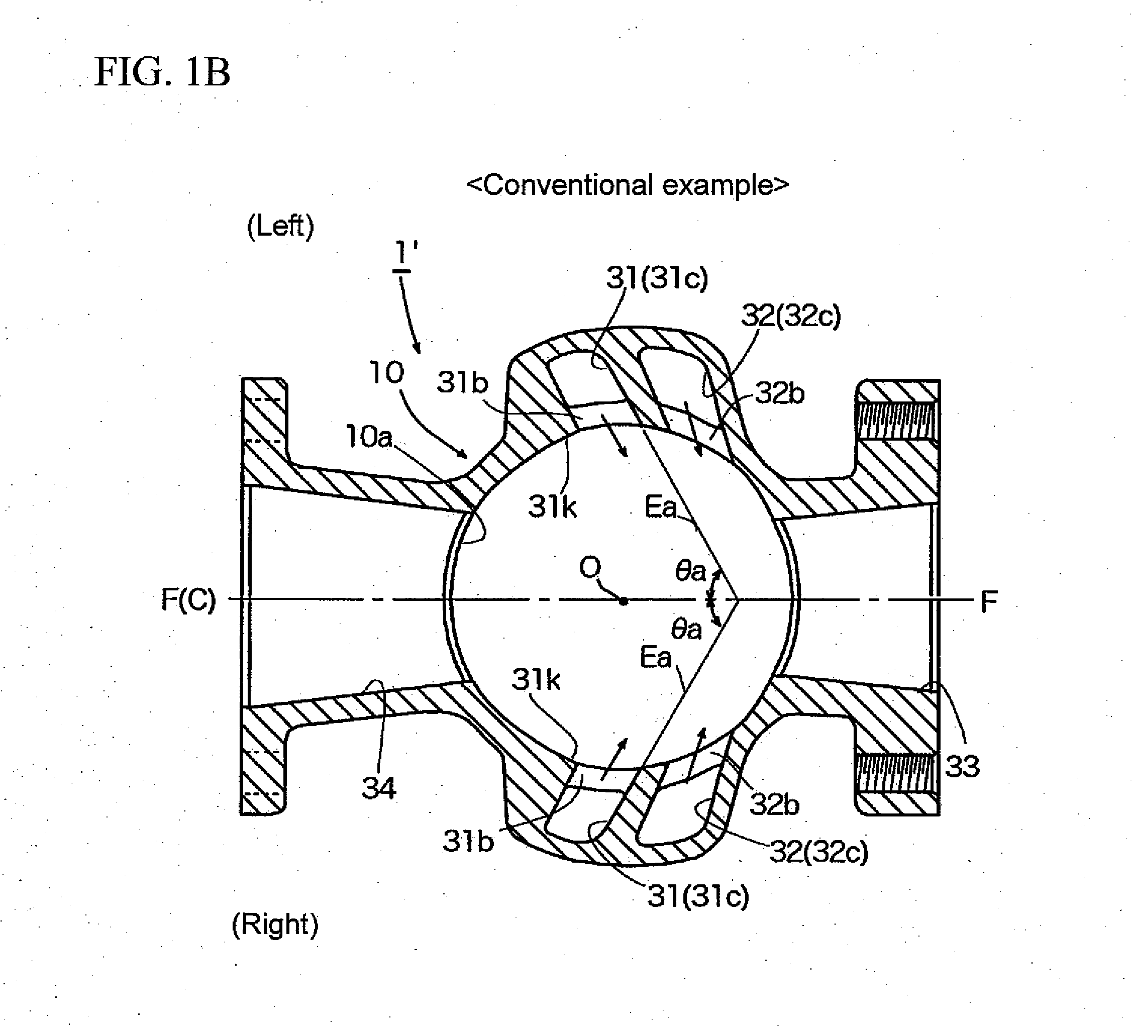
[0020]FIG. 1A is a horizontal sectional view showing a main part of one embodiment of a loop scavenged two-stroke engine according to the present invention (sectional view corresponding to a view seen along the arrows X-X of FIG. 4), FIG. 1B is a horizontal sectional view showing a main part of one example of a conventional loop scavenged two-stroke engine (sectional view corresponding to a view seen along the arrows X-X of FIG. 4), FIG. 2A is an analytical plane view provided for explanation of a scavenging flow of the embodiment of the present invention shown in FIG. 1A, FIG. 2B is an analytical plane view provided for explanation of a scavenging flow of a conventional example shown in FIG. 1B, FIG. 3A is an analytical perspective view which is provided for explanation of the scavenging flow of the embodiment of the present invention shown in FIG. 1A, FIG. 3B is an analytical pe


PUM


Abstract

A loop scavenged two-stroke internal combustion engine which can effectively restrain blow-by of fresh gas with a relatively simple configuration is provided. A horizontal scavenging angle θb in at least one spot of a scavenging passage 31L located at one side of the pair of or a plurality of pairs of left and right scavenging passages is made to differ from a horizontal scavenging angle θa of a scavenging passage 31R located at the other side, and a main flow of a scavenging flow which is blown out from the scavenging passage 31L located at the one side and a main flow of a scavenging flow which is blown out from the scavenging passage 31R which is located at the other side intersect each other or collide with each other in plane view in a region displaced in a lateral direction from a center line C of an opening of an exhaust port 34.

Description


Claims


Application Information

Patent Timeline
Owner YAMABIKO CORP
Why Eureka
Try Eureka