Hydraulic orifice

Active Publication Date: 2012-03-08
HYUNDAI MOTOR CO LTD
View PDF1 Cites 0 Cited by
  • Summary
  • Abstract
  • Description
  • Claims
  • Application Information

AI Technical Summary

Benefits of technology

[0014]Various aspects of the present invention are directed to provide a hydraulic orifice having advantages of reducing pulsation as a consequence that a joining line and at least two hydraulic lines connecting the joining line with a head oil journal are formed at a body of one piece, and oils passing through at least two hydraulic lines are joined at the joining line with different phases and to provide a hydraulic orifice which has a simple structure by using the head oil journal as a chamber. Therefore, the hydraulic orifice can be easily assembled and manufacturing cost may be reduced.

Problems solved by technology

For this purpose, the oil hydraulic line of spiral shape should be formed and it may be difficult to form the oil hydraulic line.
In addition, since the outer case and the inner case are assembled by bending the forming portion formed at the outer case toward the inner case, a diameter difference between both ends of the outer case cannot be controlled within a predetermined error range.
Since the oil hydraulic line is formed at the exterior circumference of the inner case, a part of the oil hydraulic line may be blocked when the forming portion is bent.
For this purpose, an additional tool should be necessary and it may be hard to assemble.

Method used


Image

  • Hydraulic orifice
  • Hydraulic orifice
  • Hydraulic orifice

Examples


Example

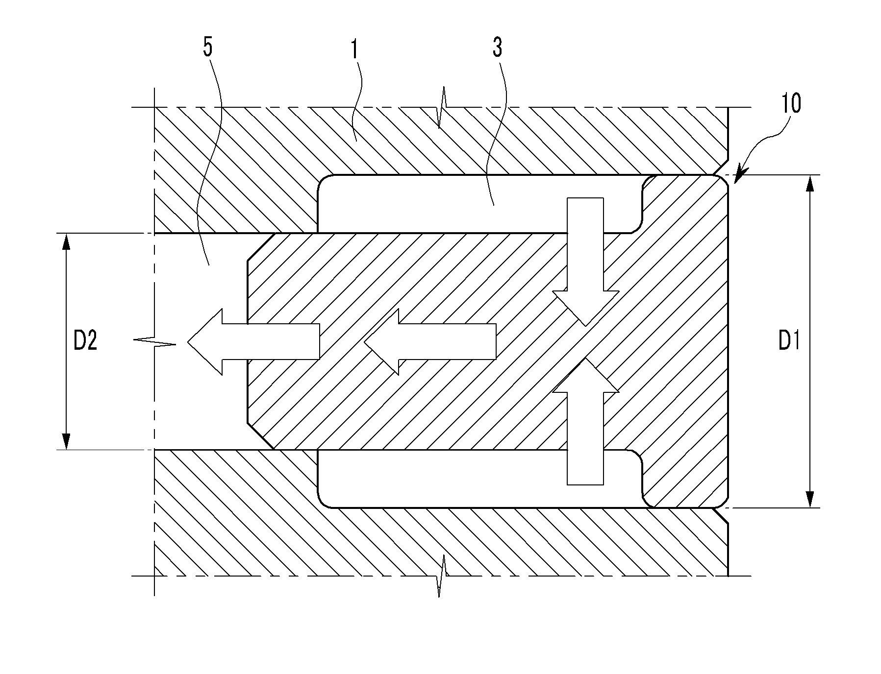
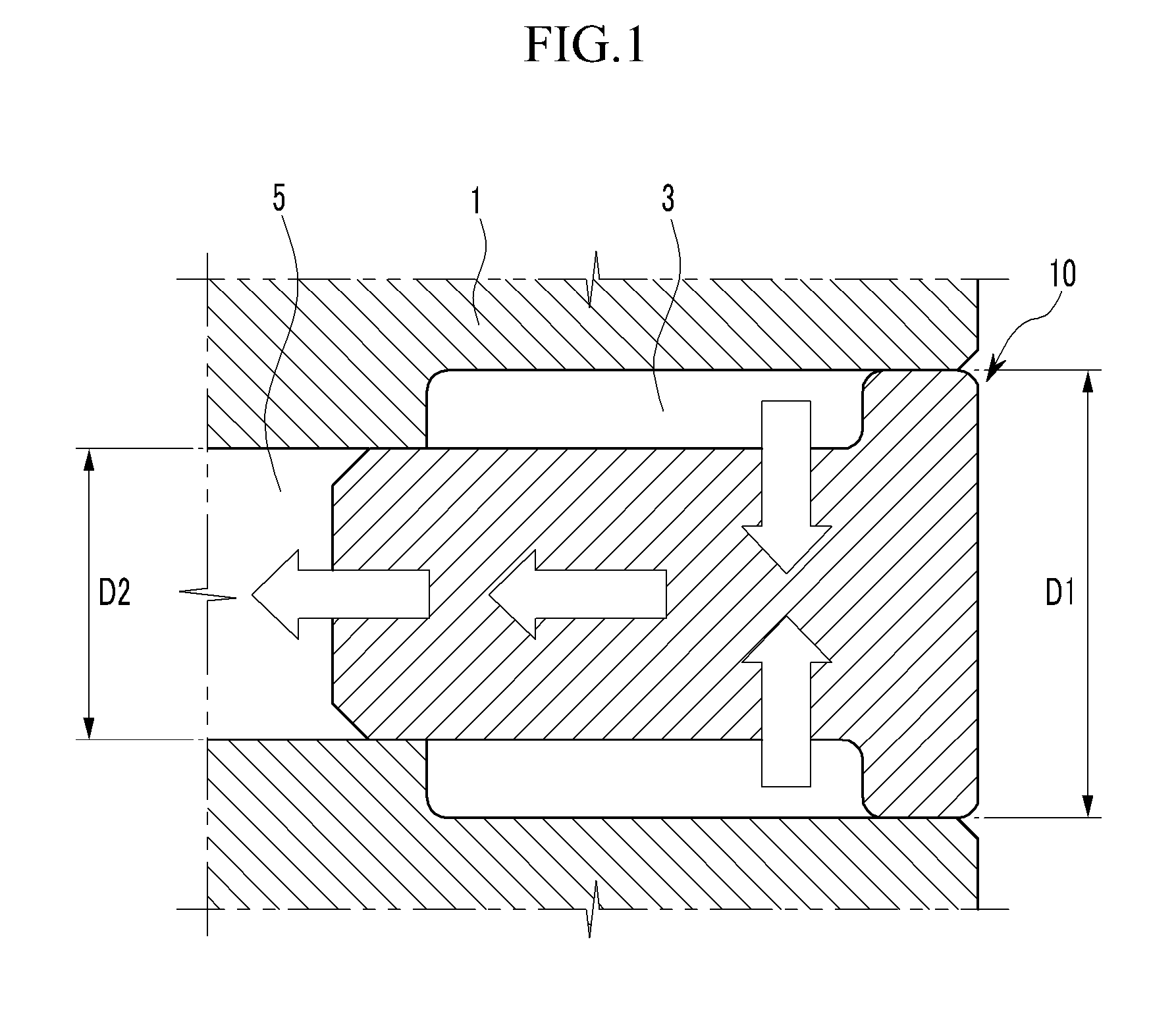
[0027]It should be understood that the appended drawings are not necessarily to scale, presenting a somewhat simplified representation of various features illustrative of the basic principles of the invention. The specific design features of the present invention as disclosed herein, including, for example, specific dimensions, orientations, locations, and shapes will be determined in part by the particular intended application and use environment.

[0028]In the figures, reference numbers refer to the same or equivalent parts of the present invention throughout the several figures of the drawing.

DETAILED DESCRIPTION OF THE INVENTION

[0029]Reference will now be made in detail to various embodiments of the present invention(s), examples of which are illustrated in the accompanying drawings and described below. While the invention(s) will be described in conjunction with exemplary embodiments, it will be understood that present description is not intended to limit the invention(s) to those e


PUM


Abstract

A hydraulic orifice which is mounted at a head oil journal formed in a cylinder head and supplies an oil to a supply line after reducing pulsation of the oil supplied to the head oil journal, may include a body pressed on the head oil journal so as to form a chamber with the cylinder head, a joining line formed along a longitudinal axis of the body therein and fluid-communicating with the supply line, and at least two hydraulic lines formed in the body and connecting the chamber with an end of the joining line in the body to supply the oil through the other end thereof to the supply line, wherein the oils passing through the at least two hydraulic lines are joined at the end of the joining line with different phases such that the pulsation of the oil in the joining line is reduced.

Description


Claims


Application Information

Patent Timeline
Owner HYUNDAI MOTOR CO LTD
Why Eureka
Try Eureka