Debris Exclusion and Retention Device for a Fuel Assembly

Active Publication Date: 2012-08-16
GLOBAL NUCLEAR FUEL -- AMERICAS
View PDF5 Cites 6 Cited by
  • Summary
  • Abstract
  • Description
  • Claims
  • Application Information

AI Technical Summary

Benefits of technology

[0007]The various embodiments of the invention provide a retention device that advantageously utilizes natural flow paths within a lower tie plate of a fuel assembly to entrap filtered debris within the lower tie plate. The problem of retention of the debris is solved, as the retention device entraps debris that has been impeded by an exclusion device, such as an independent or integral debris filter. Together, the exclusion device and the retention device cooperate to contin

Problems solved by technology

More specifically, according to one aspect, the exemplary retention devices are configured such that the coolant flow through the center opening of an inlet nozzle of the lower tie plate has a higher flow velocity than t

Method used


Image

  • Debris Exclusion and Retention Device for a Fuel Assembly
  • Debris Exclusion and Retention Device for a Fuel Assembly
  • Debris Exclusion and Retention Device for a Fuel Assembly

Examples


Embodiment Construction

[0026]As required, detailed embodiments are disclosed herein. It must be understood that the disclosed embodiments are merely exemplary of and may be embodied in various and alternative forms, and combinations thereof. As used herein, the word “exemplary” is used expansively to refer to embodiments that serve as illustrations, specimens, models, or patterns. The figures are not necessarily to scale and some features may be exaggerated or minimized to show details of particular components. In other instances, well-known components, systems, materials, or methods that are known to those having ordinary skill in the art have not been described in detail in order to avoid obscuring the present disclosure. Therefore, specific structural and functional details disclosed herein are not to be interpreted as limiting, but merely as a basis for the claims and as a representative basis for teaching one skilled in the art.

Exemplary Environment

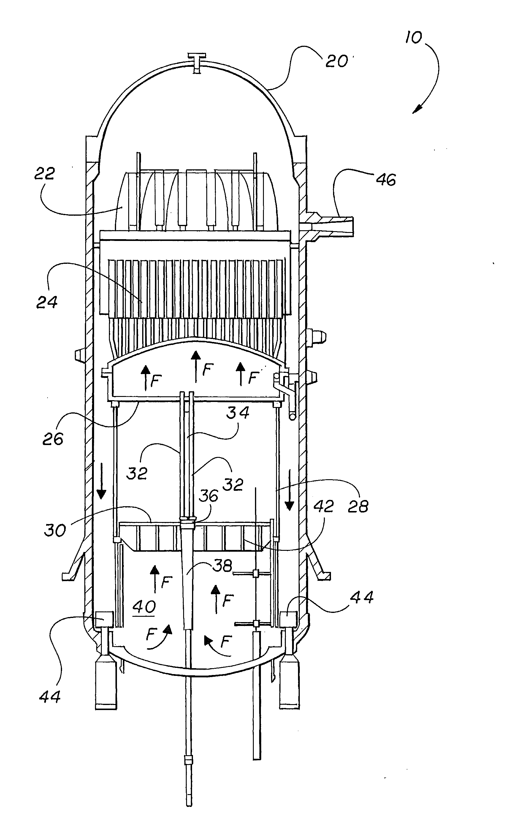
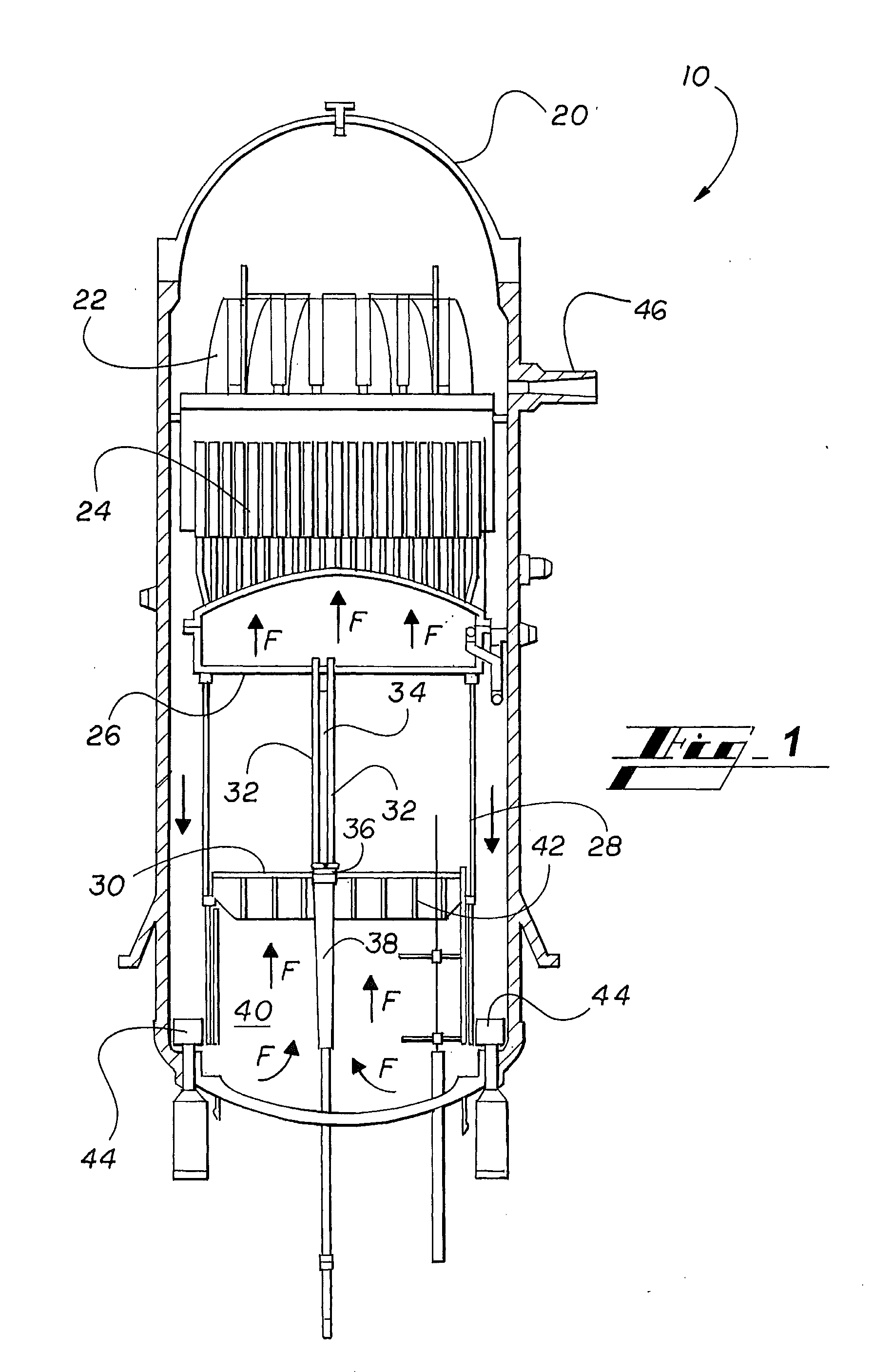
[0027]The exemplary environment in which the various em


PUM


Abstract

A debris exclusion and retention device traps and retains foreign material within the lower tie plate of the fuel assembly utilizing the existing flow paths within the lower tie plate, and without redirecting coolant flow. Flow through the inlet nozzle of the lower tie plate into an enlarged lower tie plate housing creates strong jet impingement against the center of the lower tie plate grid or debris filter, if present, which has a tendency to push debris to the periphery of the lower tie plate. Low flow zones around the periphery of the lower tie plate allow debris to fall back toward the inlet nozzle. The retention device traps and retains debris in these low flow zones without impacting existing flow patterns in the lower tie plate. Thus, the retention device has minimal or no impact on lower tie plate pressure drop.

Description


Claims


Application Information

Patent Timeline
Owner GLOBAL NUCLEAR FUEL -- AMERICAS
Why Eureka
Try Eureka