Master unit, remote unit and multiband transmission system

a multi-band transmission system and master unit technology, applied in the direction of duplex signal operation, synchronisation signal speed/phase control, electromagnetic repeaters, etc., can solve the problems of inability to cleanly separate the frequency bands on the receiver side, inability to achieve the intermodulation of the frequency bands used, and inability to achieve clean separation of the frequency bands. , to achieve the effect of reducing the intensity of the reference frequency signal, reducing the characteristic of the data signal, and facilitating

Active Publication Date: 2012-10-11
ANDREW WIRELESS SYST GMBH
View PDF6 Cites 25 Cited by
  • Summary
  • Abstract
  • Description
  • Claims
  • Application Information

AI Technical Summary

Benefits of technology

This patent describes a method called spread sequencer that uses a specific type of device called a reference frequency generator (RF) to generate signals at different frequencies. These signals are then combined together by adding them together to make it easier to remove any unwanted signals without affecting the desired ones.

Problems solved by technology

The technical problem addressed in this patent is how to efficiently distribute and combine signals sent over various networks while maintaining their quality.

Method used


Image

  • Master unit, remote unit and multiband transmission system
  • Master unit, remote unit and multiband transmission system
  • Master unit, remote unit and multiband transmission system

Examples


Embodiment Construction

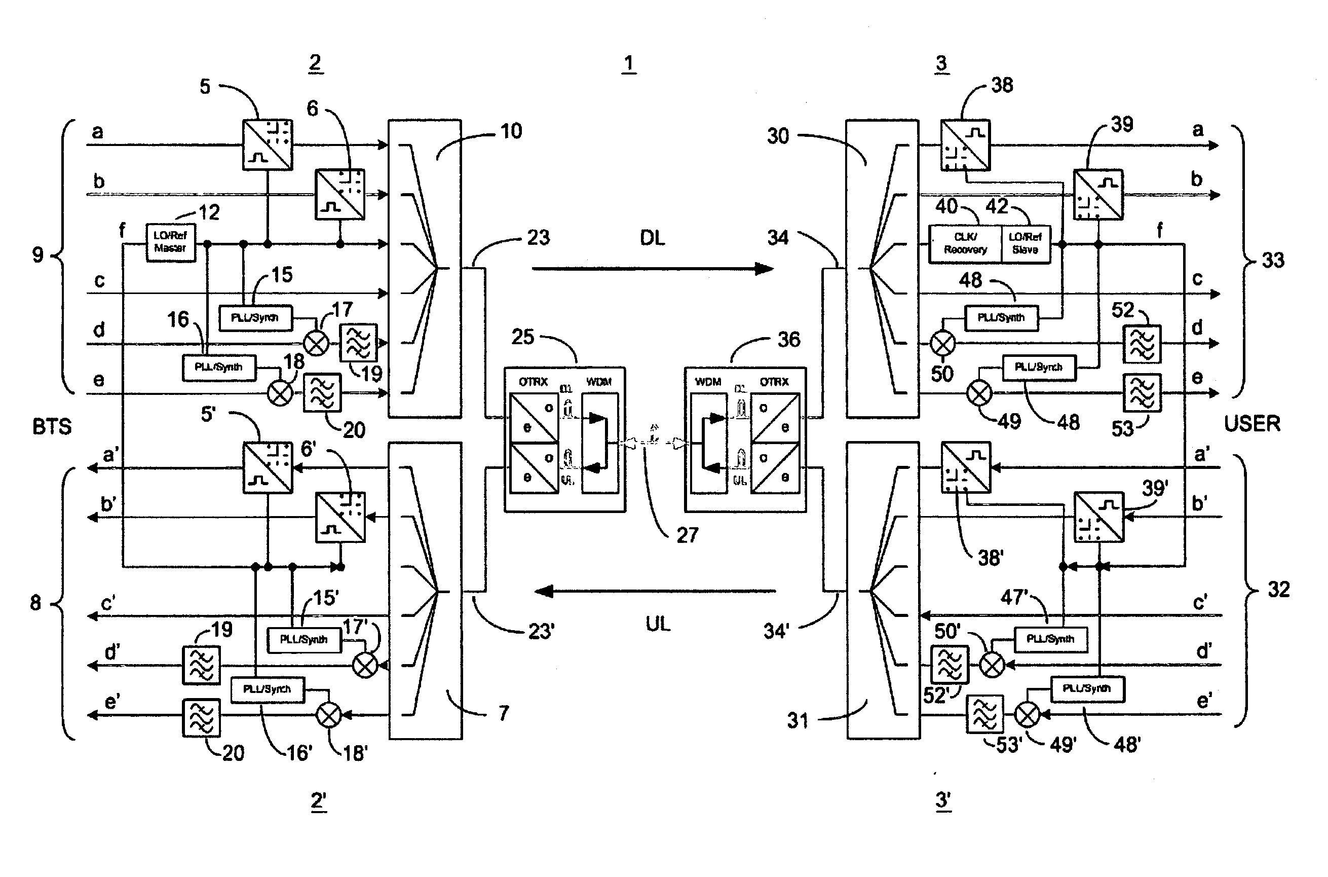
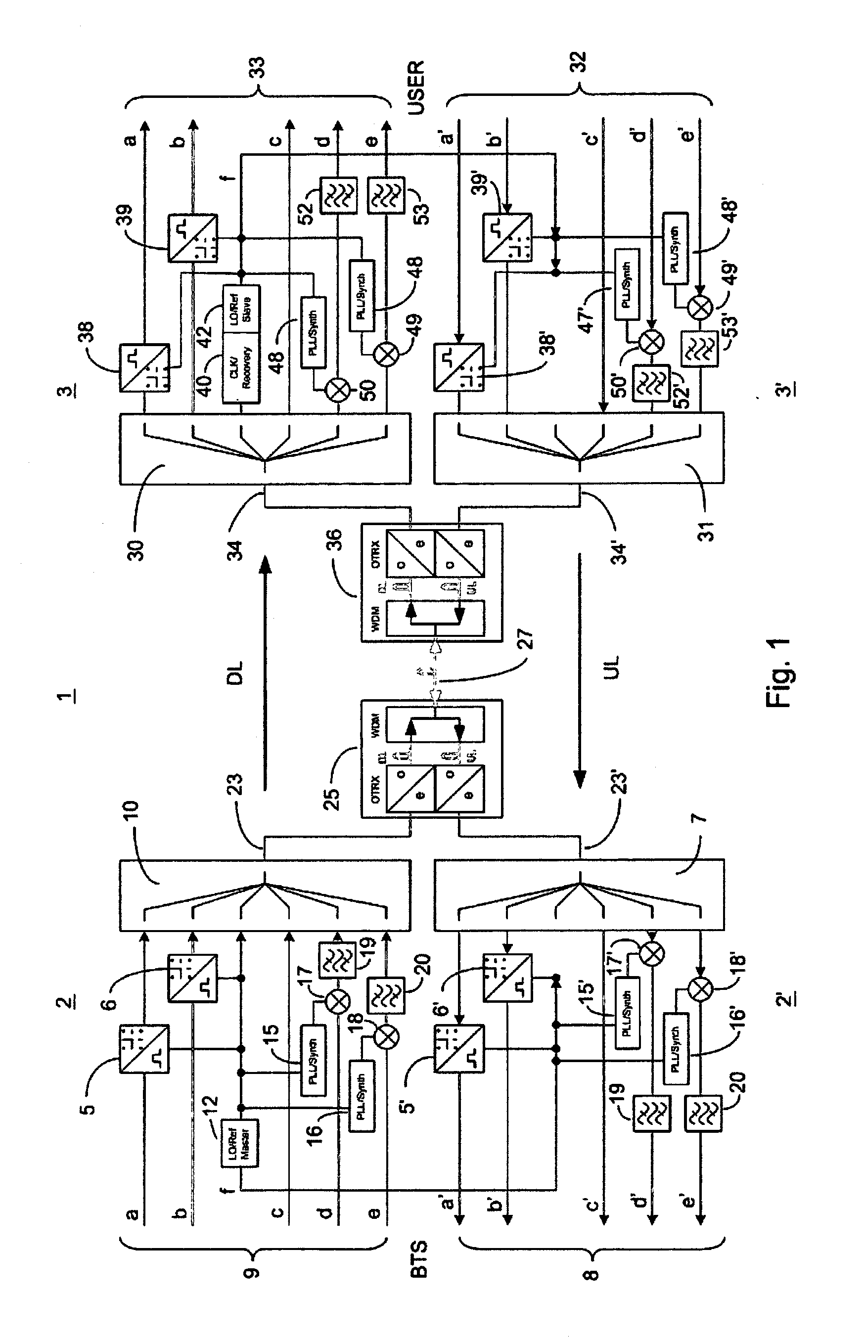
[0043]FIG. 1 shows diagrammatically the common transmission of signals of two digital networks and of signals of three wireless communication networks between a master unit 2, 2′ and a remote init 3, 3′. The master unit 2, 2′ and the remote unit 3, 3′ together form a multiband transmission system 1 for distributing and combining signals of at least one wireless communication network and of at least one digital network. The downlink region is hereby labeled by 2, 3, while the uplink region is given by 2′ and 3′.

[0044]The master unit 2, 2′ hereby comprises signal lines a, b or a′, b′ for transmitting or exchanging signals within respectively one digital network. The digital data before transmission by means of a first master modem 5 and by means of a second master modem 6 are hereby modulated on a carrier frequency. Both master modems 5, 6 are hereby embodied for a multi QAM modulation. In the uplink direction the further master modems 5′ and 6′ are provided for the demodulation of the c


PUM


Abstract

A master unit and a remote unit is provided for a multiband transmission system for distributing and combining signals of at least one wireless communication network and at least one digital network. A reference frequency generator is arranged in the master unit, the reference frequency generator being designed to clock a master modem for converting the signals of the at least one digital network. The reference frequency signal emitted by the reference frequency signal is restored via a reference frequency receiver and is used for closing a remote modem that is located there for demodulation.

Description


Claims


Application Information

Patent Timeline
Owner ANDREW WIRELESS SYST GMBH
Why Eureka
Try Eureka