Device for Producing Dry Aerosol (Varians)

a technology of aerosol and production equipment, which is applied in the field of medical equipment, can solve the problems of inability to ensure the desired concentration of aerosol in the treatment room, and achieve the effects of high operational reliability, high quality of generated aerosol, and simplified design

Inactive Publication Date: 2012-11-01
HALOMED NORTH AMERICA
View PDF5 Cites 5 Cited by
  • Summary
  • Abstract
  • Description
  • Claims
  • Application Information

AI Technical Summary

Benefits of technology

The present invention relates to a device that produces dry aerosols efficiently without complicated designs or requiring expensive equipment. It includes a casing, an air way with a supply air flow booster, a salt mill, a grinding body with a rotating drive, aerosol concentration detectors, and a controller. An air pipe is attached to the outflow channel of the chamber, where it connects to an air passage. A gap between the chamber and mill's grinding body is 3.5mm - 10mm. This design allows for efficient operation and improved performance of the resulting product.

Problems solved by technology

The technical problem addressed in this patent is that current devices used to produce dry aerosols have difficulty ensuring a consistently high level of accuracy in delivering a certain amount of medicine or other substances into the patient's lungs during medical procedures.

Method used


Image

  • Device for Producing Dry Aerosol (Varians)
  • Device for Producing Dry Aerosol (Varians)
  • Device for Producing Dry Aerosol (Varians)

Examples


Embodiment Construction

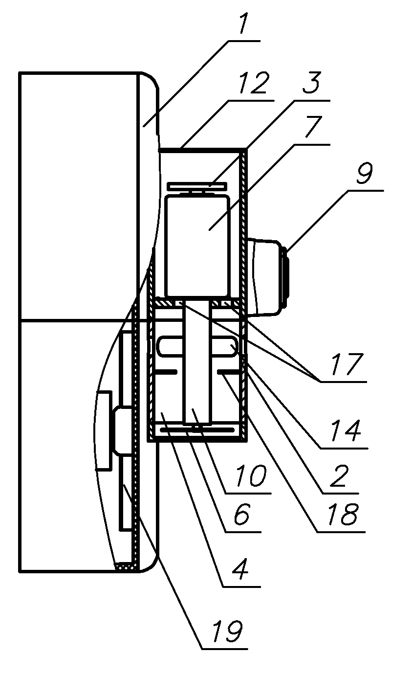
[0041]The first variant of a device for producing dry aerosol comprises a casing 1, an airway 2 with a supply air booster 3, placed in a chamber 4, joined through an outlet 5 with an airway 2, a salt mill as a grinding body 6 with a rotary drive 7, aerosol concentration detector 8, connected to a control unit 9 connected to a switch of mill drive 7, an air tube 10 is fixed in an outbound channel 5 of a chamber 4, its lower part is located atop a grinding body 6 and its upper part—in an airway 2, in the upper side of an air tube 10 there is a hole 11 directed toward an air flow in an airway 2, and a gap between the side wall of a chamber 4 and a grinding body 6 is 3-10 mm and a gap between the underside of a chamber 4 and a grinding body 6 is 1-5 mm.

[0042]In the first variant of a device for producing dry aerosol the following is preferable:

[0043]an outbound channel 5 in a chamber 4 is perpendicular to a longitudinal axis of an airway 2;

[0044]an upper part of an outbound channel 5 in a


PUM


Abstract

A device for producing dry aerosol, having a casing, an airway with a supply air flow booster, placed in a chamber, connected with an airway through an outlet, a salt mill made in the form of a grinding body with a rotary drive, aerosol concentration detector, connected to a control unit connected to a switch of mill's drive, and in accordance with the invention, an air pipe is fixed in the outbound channel of a chamber, the lower part of which is located atop a grinding body of a mill, and the upper part—in an airway, while on the upper side of an air tube there is an opening directed toward an air flow in an airway, and a gap between a chamber side and mill's grinding body is 3-10 mm, and a gap between a base of a chamber and mills' grinding body is 1-5 mm.

Description


Claims


Application Information

Patent Timeline
Owner HALOMED NORTH AMERICA
Why Eureka
Try Eureka