Heat dissipation apparatus and outdoor communication device
- Summary
- Abstract
- Description
- Claims
- Application Information
AI Technical Summary
Benefits of technology
Problems solved by technology
Method used
Image

Examples
embodiment 1
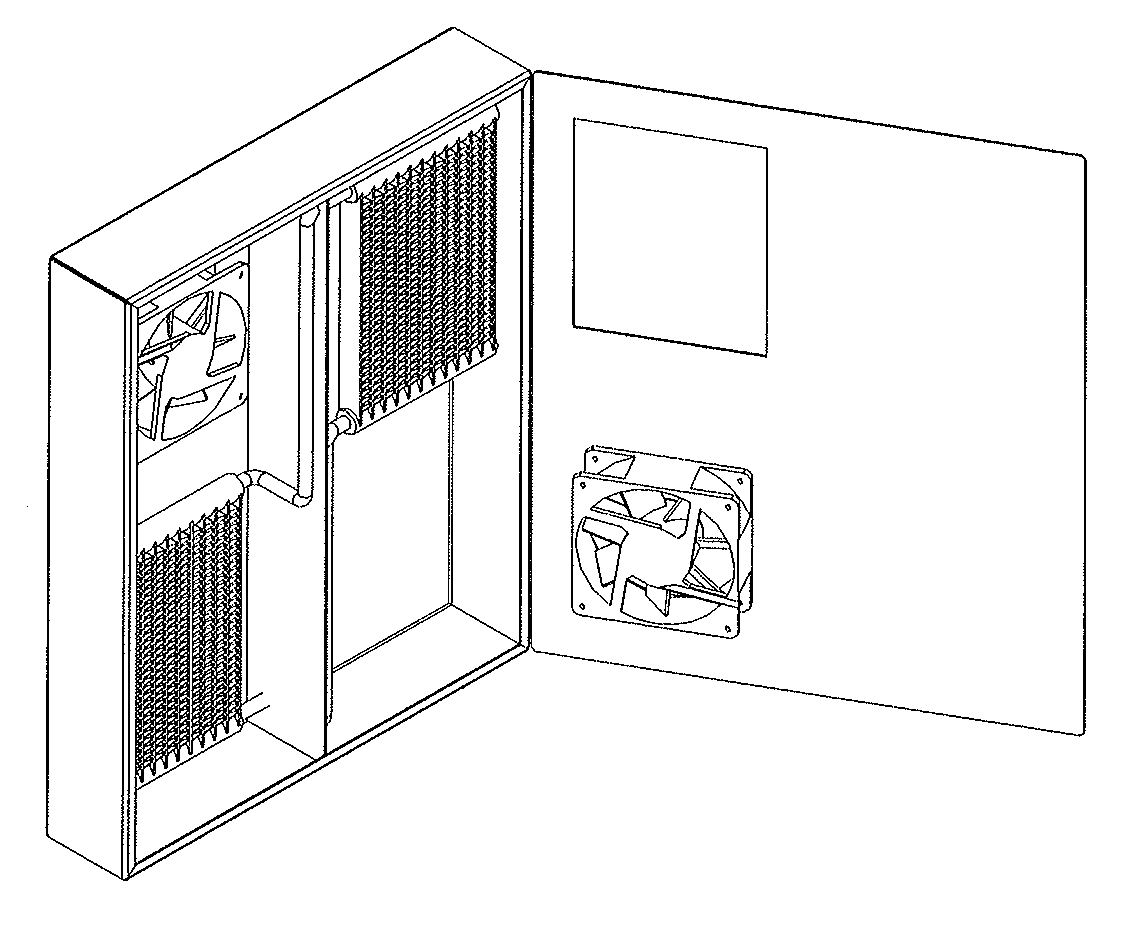
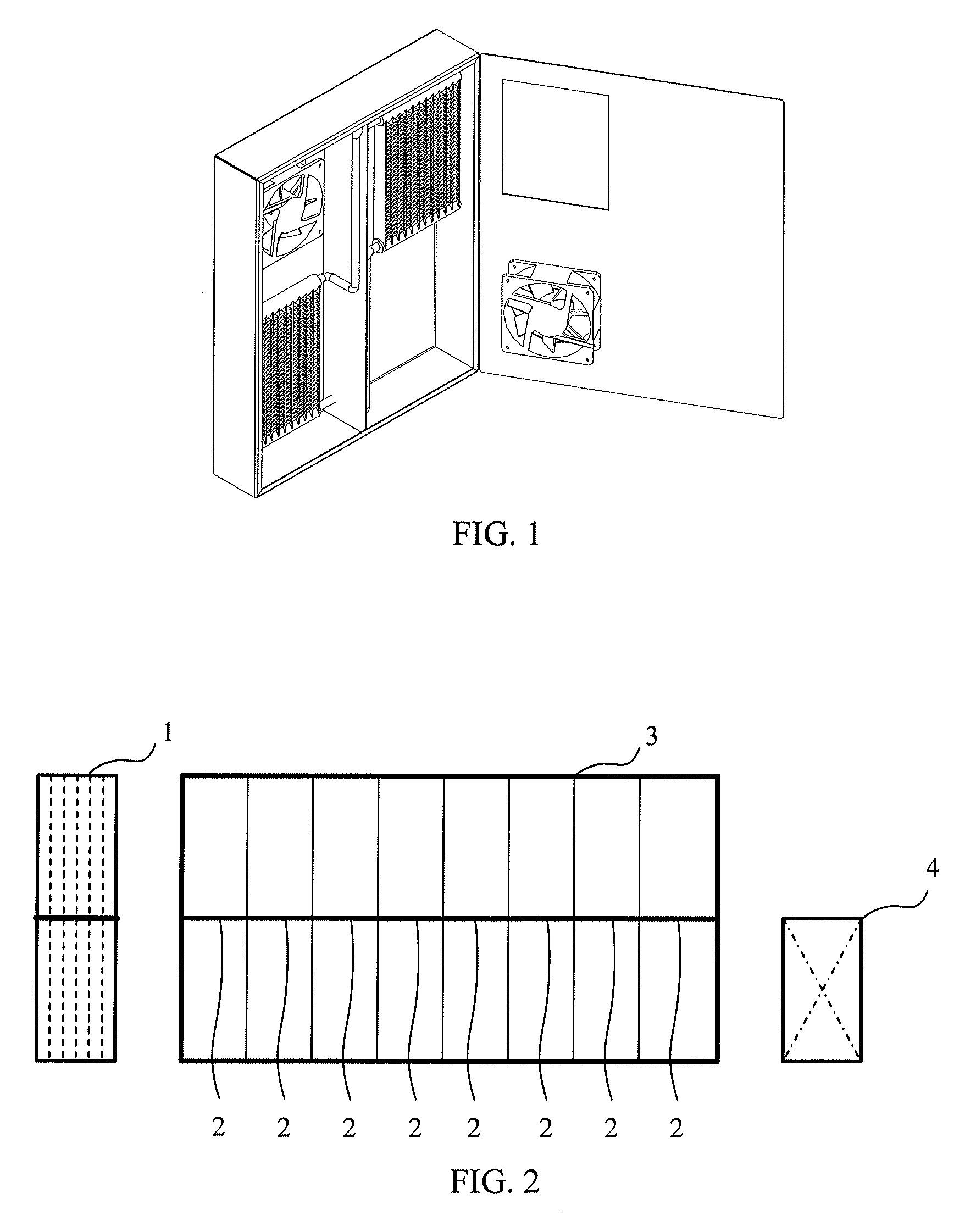
[0020]FIG. 2 is a schematic structural diagram of an unassembled heat dissipation apparatus according to As shown in FIG. 2, the heat dissipation apparatus at least comprises: one or more thermosiphon heat exchange units 1, one or more first partitions 2, and a frame 3 having at least two lattices. Particularly, each of the one or more thermosiphon heat exchange units 1 is embedded in one lattice of the at least two lattices. Each lattice of the at least two lattices having no thermosiphon heat exchange unit 1 embedded is disposed with the first partition 2 to partition the lattice into an upper portion and a lower portion, where the first partition 2 is detachable.
[0021]Based on the above technical solution, the heat dissipation apparatus may further comprise: at least a fan unit 4. Particularly, each fan unit 4 is embedded in a half lattice constructed by the frame 3 and a first partition 2.
embodiment 2
[0022]Hereinafter, through Embodiment 2, a detail description will be given for the thermosiphon heat exchange unit 1 of the above technical solution.
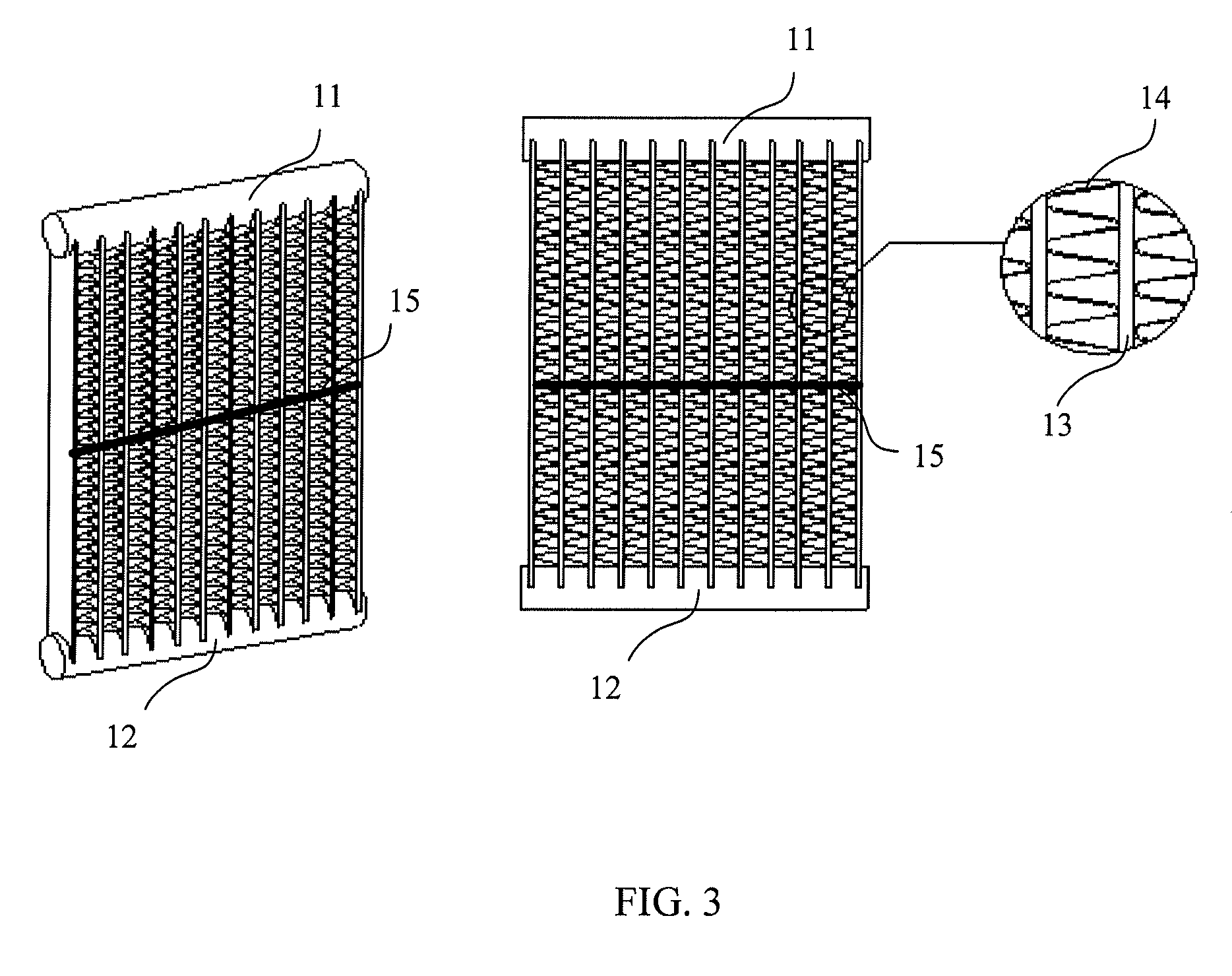
[0023]FIG. 3 is a schematic structural diagram of a thermosiphon heat exchange unit according to Embodiment 2. In the Embodiment 2, the thermosiphon heat exchange unit 1 is an enhanced heat exchange fin type thermosiphon tube. As shown in FIG. 3, each of the one or more thermosiphon heat exchange units 1 comprises: a condensation end collection pipe 11 in the upper portion of the thermosiphon heat exchange unit, a vapor end collection pipe 12 in the lower portion of the thermosiphon heat exchange unit, at least two cooling tubules 13 which are connected to the vapor end collection pipe 12 and the condensation end collection pipe 11, cooling fins 14 evenly distributed between every two cooling tubules 13, and a second partition 15 partitioning the thermosiphon heat exchange unit 1 into an upper portion and a lower portion.
[0024]The cooling
embodiment 3
[0029]In practical applications, the number of the thermosiphon heat exchange units 1 is determined according to required heat dissipation performance. W hen the outdoor communication device where the heat dissipation apparatus is located is updated, first partitions 2 in lattices having no thermosiphon heat exchange units 1 embedded currently can be removed to embed new thermosiphon heat exchange units 1, so that heat dissipation performance of the heat dissipation apparatus can be improved. In Embodiment 3, only 2 thermosiphon heat exchange units 1 are provided as an example.
[0030]Furthermore, the number of fan units 4 also can be determined according to required heat dissipation performance. When it is required to improve heat dissipation performance, newly added fan units 4 can be embedded in half lattices constructed by the frame 3 and first partitions 2. Also, according to the strength of air flow in the internal circulation air passage and the external circulation air passage, t
PUM
 Abstract
Description
Claims
Application Information
 - R&D Engineer
- R&D Manager
- IP Professional
- Industry Leading Data Capabilities
- Powerful AI technology
- Patent DNA Extraction
Browse by: Latest US Patents, China's latest patents, Technical Efficacy Thesaurus, Application Domain, Technology Topic.
© 2024 PatSnap. All rights reserved.Legal|Privacy policy|Modern Slavery Act Transparency Statement|Sitemap