Image capturing apparatus and control method for image capturing apparatus
a technology of image capturing apparatus and control method, which is applied in the direction of instruments, television systems, focusing aids, etc., can solve the problems of increasing noise, worsening s/n ratio of image signal, and increasing noise, so as to maintain the output rate of video signal and improve the s/n ratio
- Summary
- Abstract
- Description
- Claims
- Application Information
AI Technical Summary
Benefits of technology
Problems solved by technology
Method used
Image

Examples
first embodiment
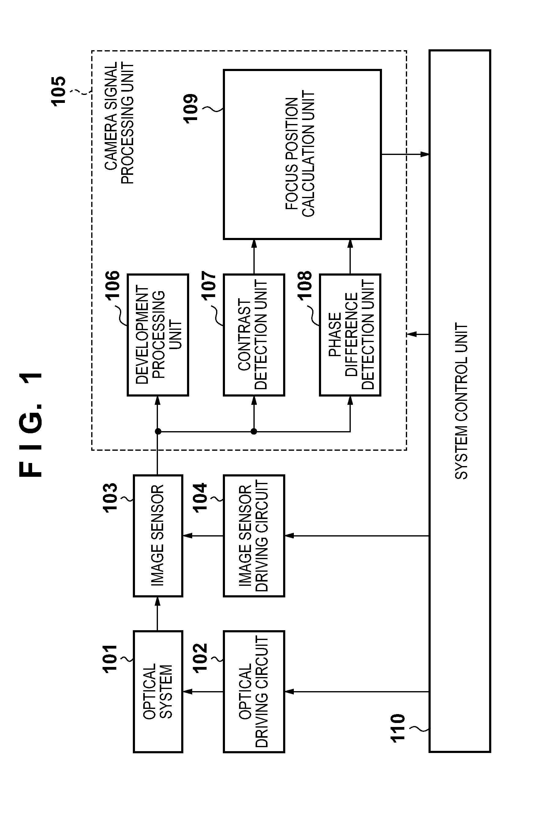
[0030]FIG. 1 is a block diagram showing a schematic configuration of an image capturing apparatus according to the first embodiment. In FIG. 1, 101 denotes an optical system composed of at least one of a zoom lens, diaphragm and focus lens, and 102 denotes an optical driving circuit that controls the optical system 101 in accordance with drive information for the optical system 101 output from a system control unit 110, which will be described later.
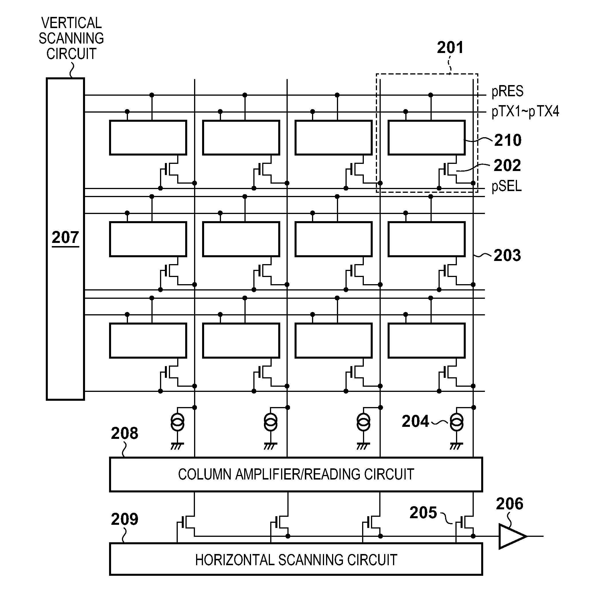
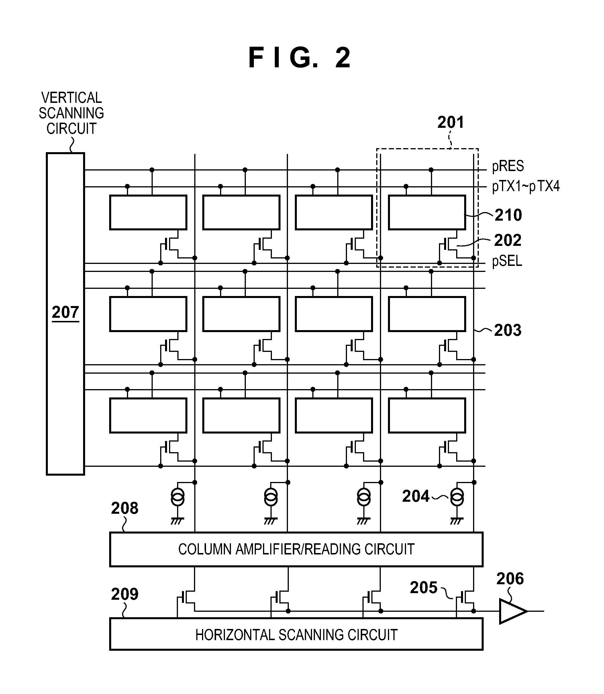
[0031]Also, 103 denotes an image sensor that photoelectrically converts an image of the subject formed by the optical system 101 into an electrical signal and outputs the electrical signal as an image signal, and 104 denotes an image sensor driving circuit that controls the image sensor 103 in accordance with drive information for the image sensor 103 output from the system control unit 110, which will be described later. When the image sensor 103 has an electronic shutter function, a control signal output from the image sensor driving circ
second embodiment
[0066]A description is now given of a second embodiment of the present invention. FIG. 12 is a block diagram showing a schematic configuration of an image capturing apparatus according to the second embodiment. Note that the constituent elements of FIG. 12 that are similar to those explained in the first embodiment with reference to FIG. 1 are given the same reference numbers thereas, and a description thereof is omitted. The feature of the second embodiment is that the driving of the image sensor 103 is switched in accordance with the brightness of the subject acquired from image signals and the imaging mode of the image capturing apparatus.
[0067]As shown in FIG. 12, an image capturing apparatus according to the second embodiment includes an AE evaluation value calculation unit 120 for acknowledging the brightness of the subject in addition to the constituent elements shown in FIG. 1. The AE evaluation value calculation unit 120 calculates a luminance level of the subject being imaged
third embodiment
[0076]A description is now given of a third embodiment of the present invention. FIG. 15 is a block diagram showing a schematic configuration of an image capturing apparatus according to the third embodiment. Note that the constituent elements of FIG. 15 that are similar to those explained in the first embodiment with reference to FIG. 1 are given the same reference numbers thereas, and a description thereof is omitted. The feature of the third embodiment is that the driving of the image sensor 103 is switched in accordance with the motion amount of the subject and the motion amount of the image capturing apparatus itself acquired from an image signal.
[0077]In FIG. 15, a motion amount calculation unit 131 is provided as means for acknowledging the motion amount of the subject. The motion amount of the subject being imaged by the image capturing apparatus is calculated from the image signal acquired from the image sensor 103, and the calculated motion amount is transmitted to the system
PUM
 Abstract
Description
Claims
Application Information
 - R&D Engineer
- R&D Manager
- IP Professional
- Industry Leading Data Capabilities
- Powerful AI technology
- Patent DNA Extraction
Browse by: Latest US Patents, China's latest patents, Technical Efficacy Thesaurus, Application Domain, Technology Topic.
© 2024 PatSnap. All rights reserved.Legal|Privacy policy|Modern Slavery Act Transparency Statement|Sitemap