Flood protection gate for vehicular & pedestrian traffic

Inactive Publication Date: 2013-06-20
OBERMEYER HENRY K
View PDF3 Cites 9 Cited by
  • Summary
  • Abstract
  • Description
  • Claims
  • Application Information

AI Technical Summary

Benefits of technology

[0003]Accordingly, it is the object of this invention to provide a water control gate system that provides for easy an

Problems solved by technology

Conventional bottom hinged water control gates are fitted with irregularly shaped hinges and reinforcing rib

Method used


Image

  • Flood protection gate for vehicular & pedestrian traffic
  • Flood protection gate for vehicular & pedestrian traffic
  • Flood protection gate for vehicular & pedestrian traffic

Examples


Embodiment Construction

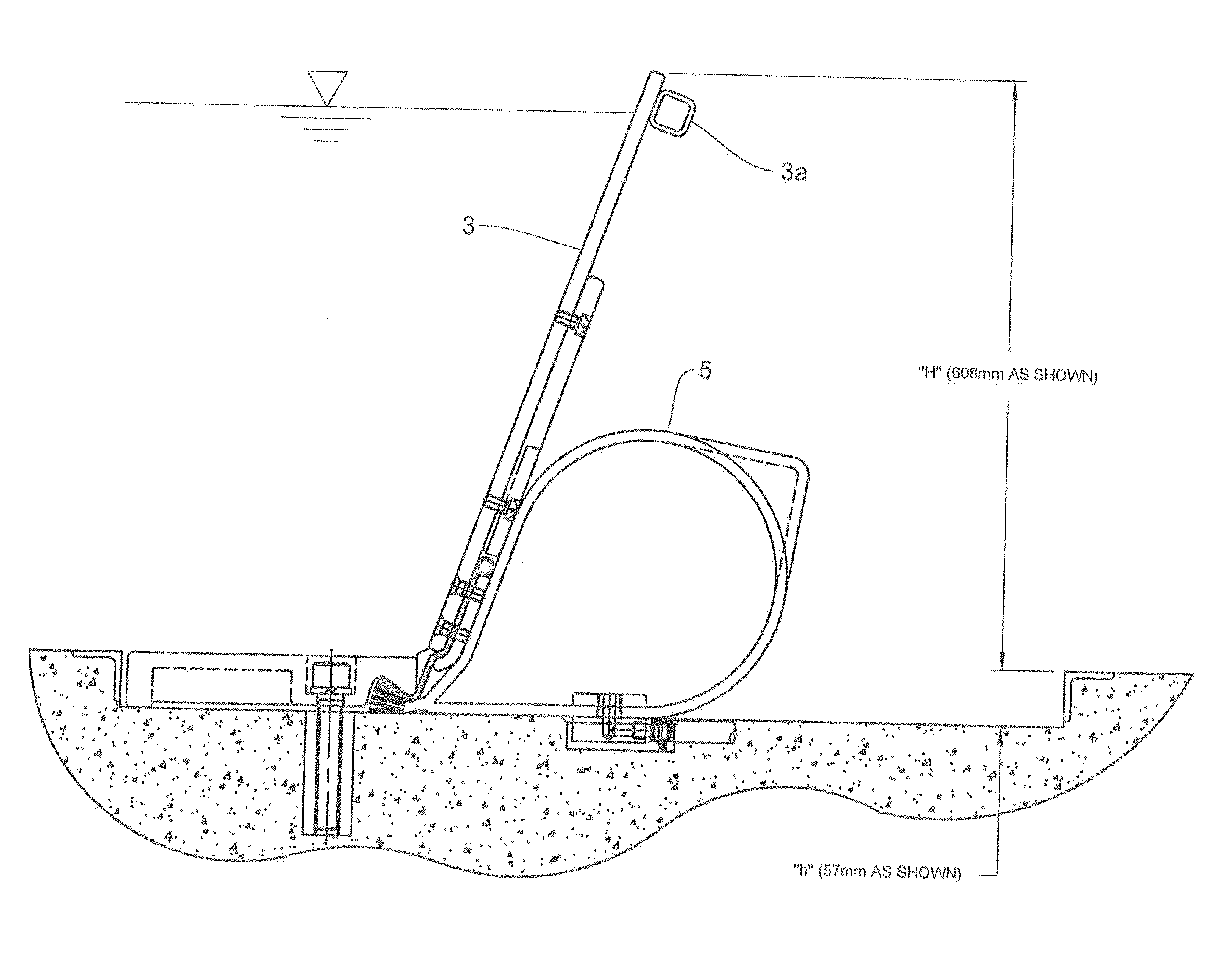
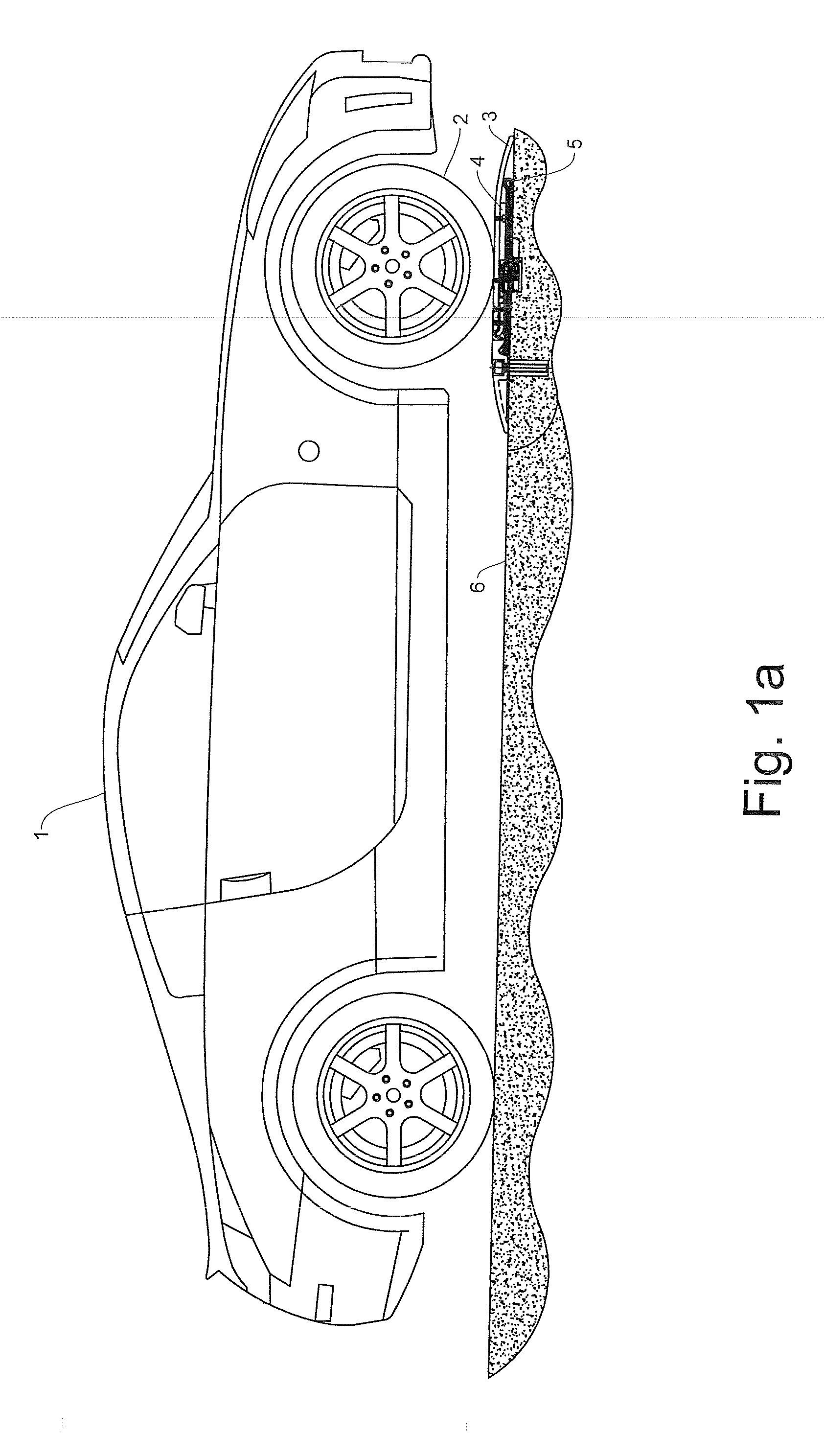
[0021]Referring now to FIG. 1a, automobile 1 transmits by its tire 2 a portion of its weight to gate panel 3 which in turn compresses spacer 4 onto air bladder 5 which in turn transmits its load to roadway surface 6.

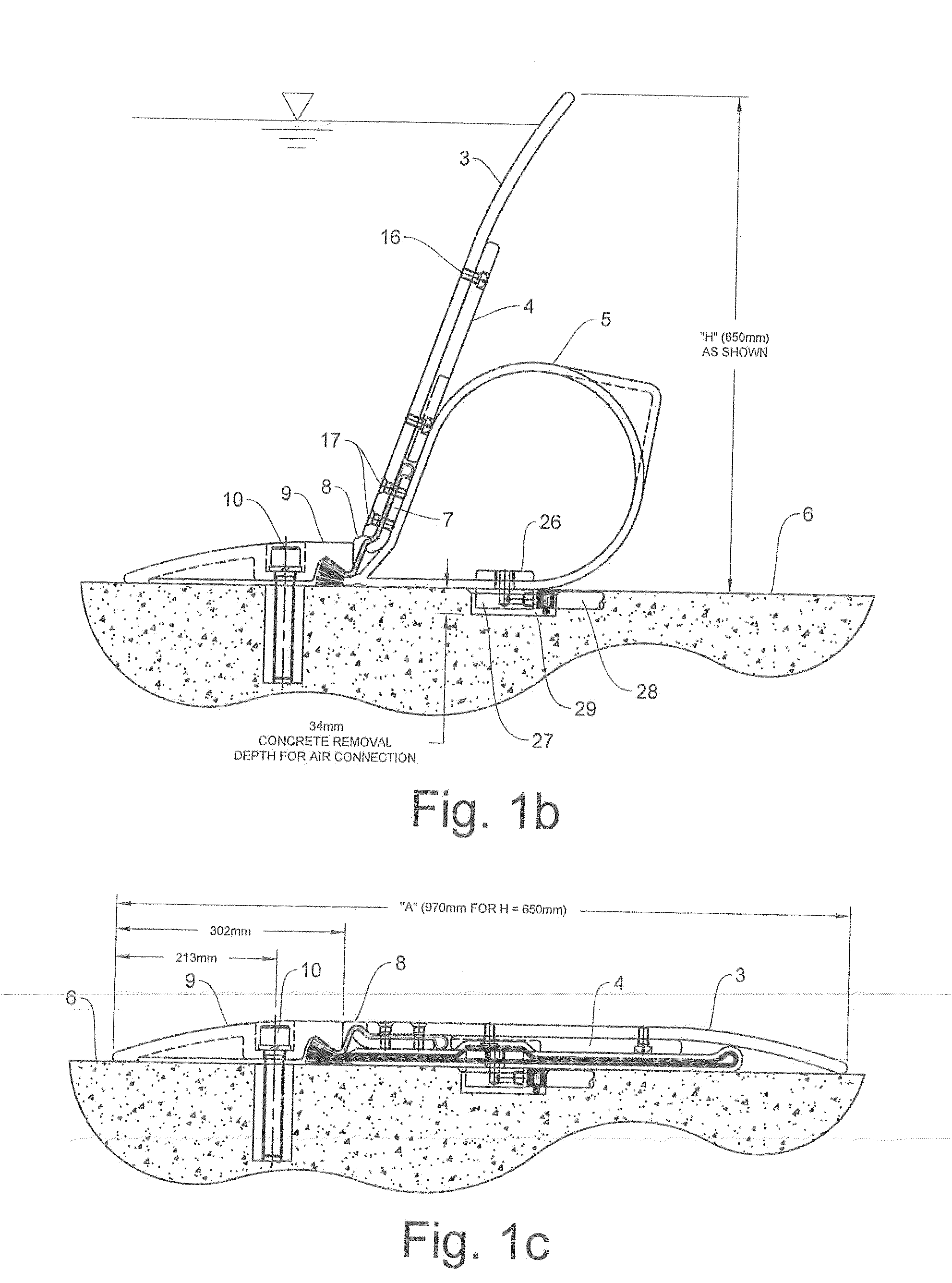
[0022]Referring now to FIG. 1b, a detailed cross section is shown, in the gate-raised position, of the gate assembly of FIG. 1a. Hinge flap 8 is clamped to gate panel 3 by means of hinge retainer 7 and hinge retainer bolts 17. Hinge flap 8 is secured on its upstream end by clamp 9.

[0023]Referring to FIG. 1c, hinge flap 8 is preferably molded in its gate-lowered configuration in which position it presents a flush flat surface to pedestrian and vehicular traffic. Clamp 9 is secured to roadway 6 by means of anchors 10. Spacer 4 is bolted to gate panel 3 by means of bolts 16. The air connection to the air bladder 5 is comprised of upper fitting portion 26 and lower fitting portion 27. The air connection is connected to air supply hose 28.

[0024]Referring to FIG. 1d, locking stru


PUM


Abstract

The invention relates to a roadway flood protection and traffic barrier which provides a smooth upper surface for vehicles, pedestrians, etc. and is thin enough to be mounted to the surface of an existing roadway or parking garage ramp, for example. A hinge mechanism is disclosed which facilitates the provision of a smooth roadway surface as well as a tight seal. A locking strut is provided that keeps the gate panels raised even in case of air pressure loss and which is remotely controllable.

Description


Claims


Application Information

Patent Timeline
Owner OBERMEYER HENRY K
Why Eureka
Try Eureka