Endoscope system, processor device thereof, and exposure control method

Active Publication Date: 2013-09-19
FUJIFILM CORP
View PDF9 Cites 13 Cited by
  • Summary
  • Abstract
  • Description
  • Claims
  • Application Information

AI Technical Summary

Benefits of technology

[0019]According to the present invention, the exposure conditions are determined in accordance with the types of video images, based on the brightness of the specific video image to which a user gives the greatest attention out of the plurality of types of video images. Exposure is controlled based on the determined exposure conditions. Therefore, not only the specific video image but also the other video images have appropriate exposure. The determination of the exposure conditions is easily performed by measurement of the brightness of the specific video image.

Problems solved by technology

Therefore, the exposure control cannot be performed appropriately.

Method used


Image

  • Endoscope system, processor device thereof, and exposure control method
  • Endoscope system, processor device thereof, and exposure control method
  • Endoscope system, processor device thereof, and exposure control method

Examples


Example

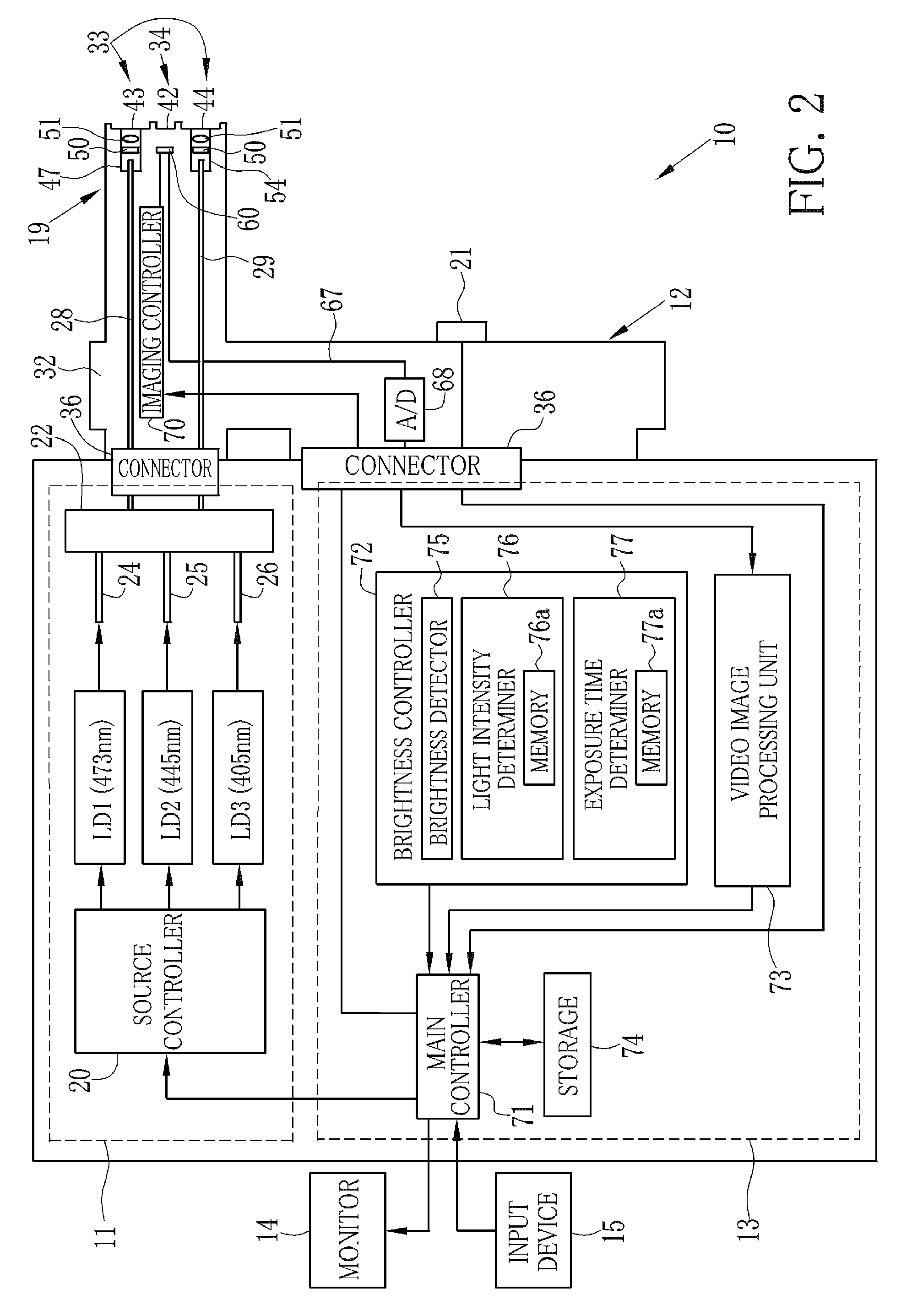
[0109]In the first embodiment, semiconductor light sources are used as the laser sources LD1 to LD3. Instead of this, a second embodiment adopts a rotary filter method in which broadband light from a white light source such as a xenon lamp is wavelength split. As shown in FIG. 19, an endoscope system 100 has the same structure as the endoscope system 10 of the first embodiment, except for an electronic endoscope 101 and a light source device 102. Therefore, the structure of the electronic endoscope 101 and the light source device 102 and parts related thereto will be described below, and explanation of the other parts will be omitted. Note that, it is difficult for the system of the second embodiment to perform control of the light intensity in a short time owing to the use of the rotary filter method. For this reason, the brightness controller 72 of the processor device 13 is not provided with the light intensity determiner 76.

[0110]The electronic endoscope 101 differs from the electr


PUM


Abstract

In a special observation mode, an oxygen saturation frame period, a normal frame period, and a vessel pattern frame period are repeatedly performed. A brightness detector detects the brightness of a latest frame image of an oxygen saturation video image, being a key video image. The intensity of light to be applied in the next oxygen saturation frame period is determined from the detected brightness. From the determined light intensity and a light intensity ratio among frames, the intensity of light to be applied in the next normal frame period and the next vessel pattern frame period is calculated. The exposure time of the next oxygen saturation frame period is determined from the detected brightness. From the determined exposure time and an exposure time ratio among frames, the exposure time of the next normal frame period and the next vessel pattern frame period is determined.

Description


Claims


Application Information

Patent Timeline
Owner FUJIFILM CORP
Why Eureka
Try Eureka