Beverage dispensing apparatus

Inactive Publication Date: 2013-10-03
MATSIE LOU
View PDF0 Cites 2 Cited by
  • Summary
  • Abstract
  • Description
  • Claims
  • Application Information

AI Technical Summary

Benefits of technology

[0007]The primary advantage of the present invention is that there is no thermal break in the tap. The present invention is integral with the cooling systems utilized in a beer tower, and the extended tap is not an extension, but rather is an integral piece. The entire unit remains chilled at the same temperature as the tank. The beer dispensing system 39 of the present invention has the ability to cool various elements of the system and maintain these elements within this acceptable temperature range.
[0008]The lower mass of the present invention allows the beverage to remain chilled while it rests in the faucet. The present invention has a wall thickness of less than 0.006 inches. The larger mass of the prior art beer tap extension acts as a heat conductor, thereby transferring the heat of the room to the beverage as it sits in the tap.
[0009]Another primary deficiency of the fast tap beverage dispensing apparatus is that it is difficult to clean, whereas the present invention can be cleaned with a bottle brush. It is well known that the residue that can accumulate in crevices of beverage taps and lines. The residue can provide substrate for bacterial growth, and bits of residue can come loose and flow into the beverage. The prior art fast tap extensions impose a seam on the tap, which allows for residue accumulation, and the extension is submerged in the beverage itself as pouring occurs. The present invention extends to the bottom of the glass, however, a user lowers the glass away from the

Problems solved by technology

Another primary deficiency of the fast tap beverage dispensing apparatus is that it is

Method used


Image

  • Beverage dispensing apparatus
  • Beverage dispensing apparatus

Examples


Embodiment Construction

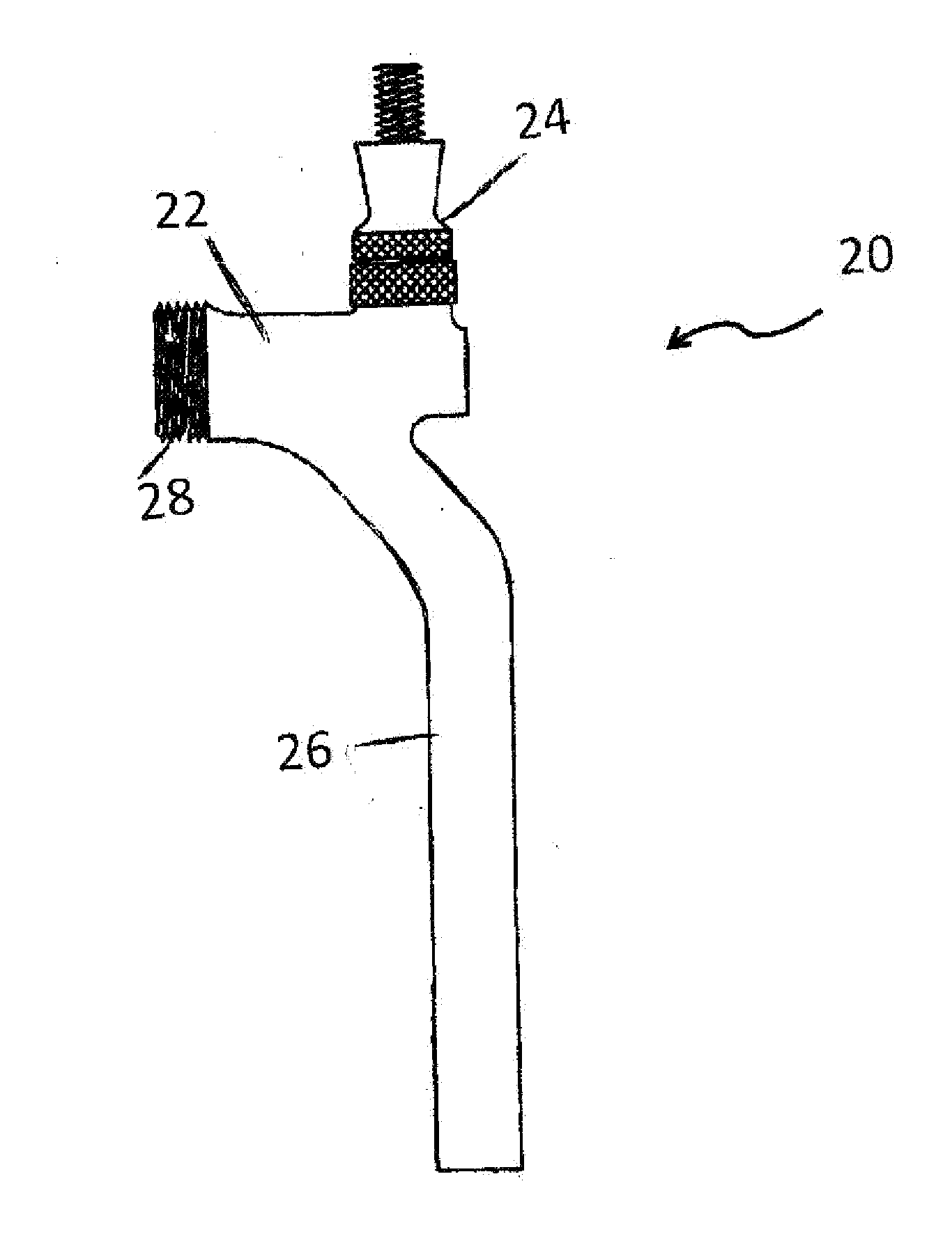
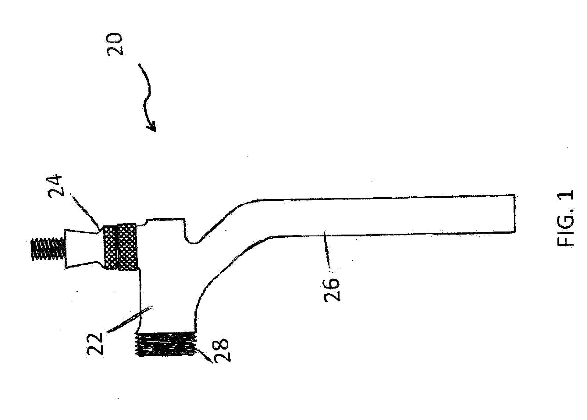
[0015]As shown in FIG. 1, the rapid beverage dispensing device 20 comprises a neck assembly 22, a valve assembly 24, and an extended nozzle 26. The neck assembly 22 is substantially vertical. The rapid beverage dispensing device 20 is designed to attach to a conventional pressurized beverage dispensing system, such as a beer dispensing system or similar beverage-containing reservoir and for conveying a beverage from a container or beer keg to the device 20. A threaded shank 28 connects the device 20 to the conventional system.

[0016]Neck assembly 22 of the rapid beverage dispensing device 20 positions and supports the rapid beverage dispensing device 20 in a manner that allows for the bottom-initiated filling of a wide variety of container sizes, for example, ranging from glasses to pitchers. The neck assembly 22 has threads 28 to attach to a standard beverage reservoir or a draft dispensing tower column.

[0017]While certain preferred embodiments of the present invention have been disclo


PUM


Abstract

A beverage dispensing device fluid has an extended conduit nozzle to permit the dispensing of a pressurized beverages at a high flow rate without producing excessive foaming comprising a streamlined valve assembly and a downward extending nozzle which permits a range of containers to be filled from the bottom without submerging the nozzle in the beverage.

Description


Claims


Application Information

Patent Timeline
Owner MATSIE LOU
Why Eureka
Try Eureka