Antenna holding device for electromagnetic measuring

Inactive Publication Date: 2013-10-31
HONG FU JIN PRECISION IND (SHENZHEN) CO LTD +1
View PDF5 Cites 8 Cited by
  • Summary
  • Abstract
  • Description
  • Claims
  • Application Information

AI Technical Summary

Problems solved by technology

However, frequently adjusting the test antenna easily changes the h

Method used


Image

  • Antenna holding device for electromagnetic measuring
  • Antenna holding device for electromagnetic measuring
  • Antenna holding device for electromagnetic measuring

Examples


Embodiment Construction

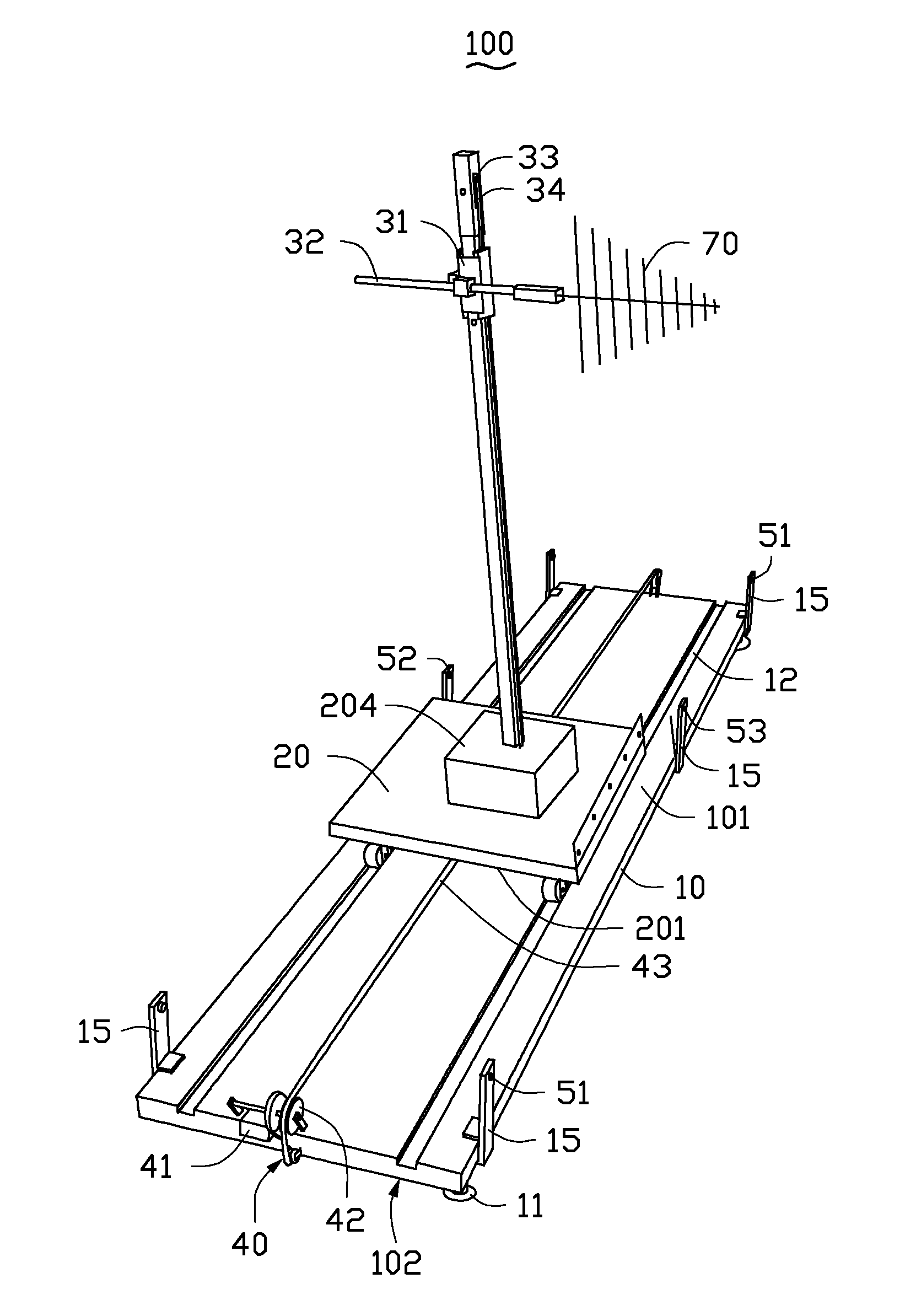
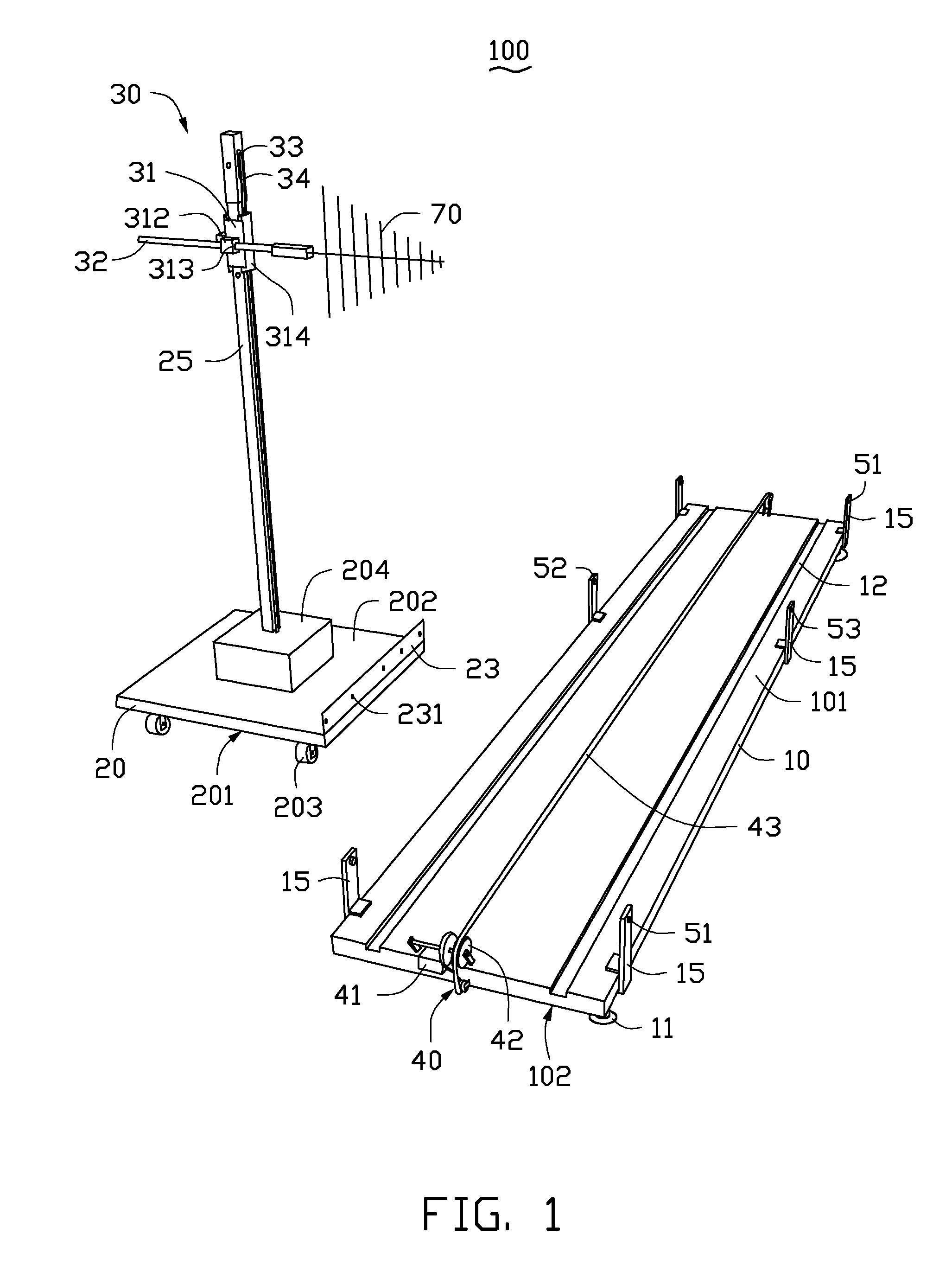
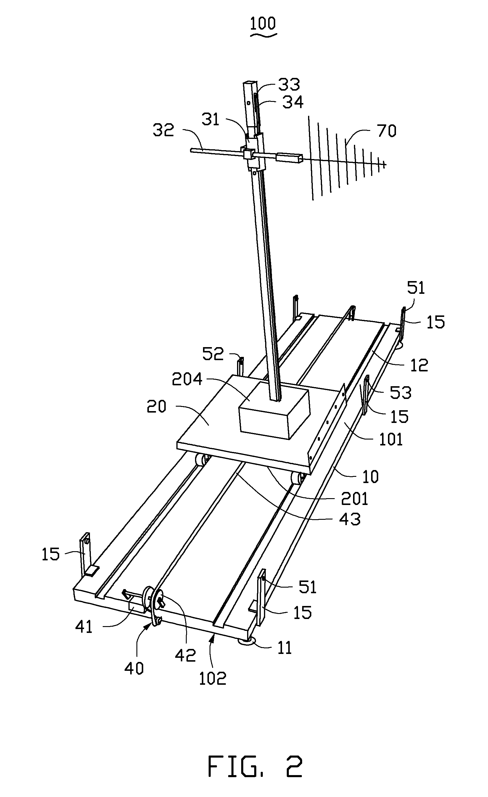
[0009]FIG. 1 and FIG. 2 show an antenna holding device 100, according to an exemplary embodiment. The antenna holding device 100 can be used to hold a test antenna for electromagnetic measurements, such as electromagnetic interference (EMI) measurements. In this embodiment, a test antenna 70 can be held on the antenna holding device 100.

[0010]The antenna holding device 100 comprises a base 10, a sliding plate 20, a holding pole 25, a first driving unit 30, a second driving unit 40, and a detection unit 50.

[0011]The base 10 is substantially a rectangular planar board, and comprises a top surface 101 and a bottom surface 102. The top surface 101 and the bottom surface 102 are parallel to each other. Four supporting feet 11 are respectively mounted on four corners of the bottom surface 102, for enabling the antenna holding device 100 to be horizontally positioned. A plurality of planar plates 15 are perpendicularly mounted on the top surface 101 of the base 10, and are all mounted on two


PUM


Abstract

An antenna holding device for holding test antennas includes a base, a sliding plate, a holding pole, a first driving unit and a second driving unit. The base defines two parallel linear sliding grooves. The sliding plate is attached to the base and is slidably engaged in the two parallel linear sliding grooves. The holding pole is perpendicularly mounted on the sliding plate. The first driving unit includes a sliding block and an antenna pole. The sliding block is slidably attached to the holding pole, and the antenna pole is mounted on the sliding block. The second driving unit is positioned on the base and drives the sliding plate to move relative to the base.

Description


Claims


Application Information

Patent Timeline
Owner HONG FU JIN PRECISION IND (SHENZHEN) CO LTD
Why Eureka
Try Eureka