Relay station, base station, transmission method, and reception method
a transmission method and relay station technology, applied in the direction of transmission path division, multiplex communication, frequency-division multiplex, etc., can solve the problems of limiting the number of relay stations, reducing the overhead of uplink resources, and reasonable costs of installation of base stations
- Summary
- Abstract
- Description
- Claims
- Application Information
AI Technical Summary
Benefits of technology
Problems solved by technology
Method used
Image

Examples
embodiment 1
[0048][Overview of Communication System]
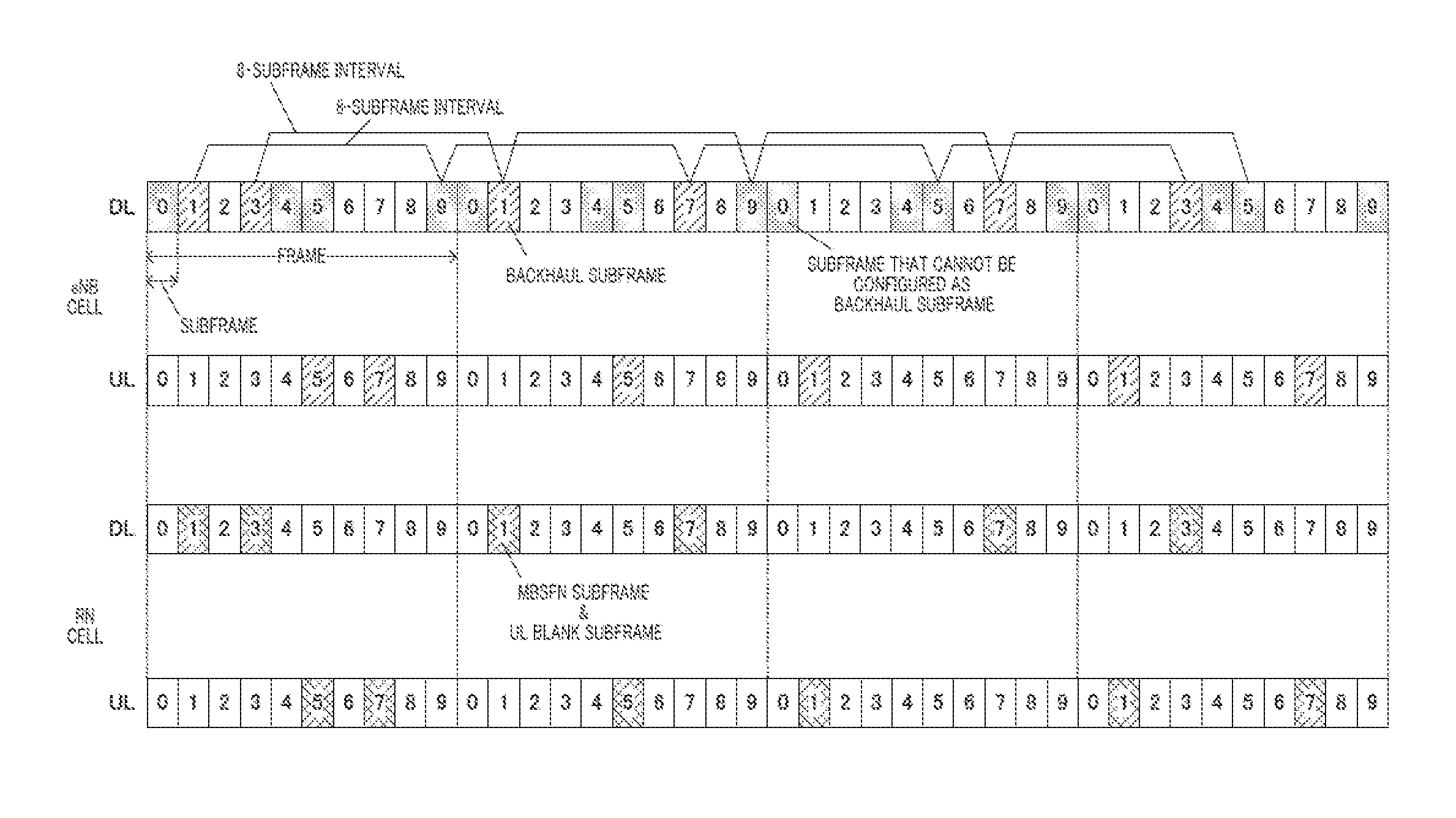
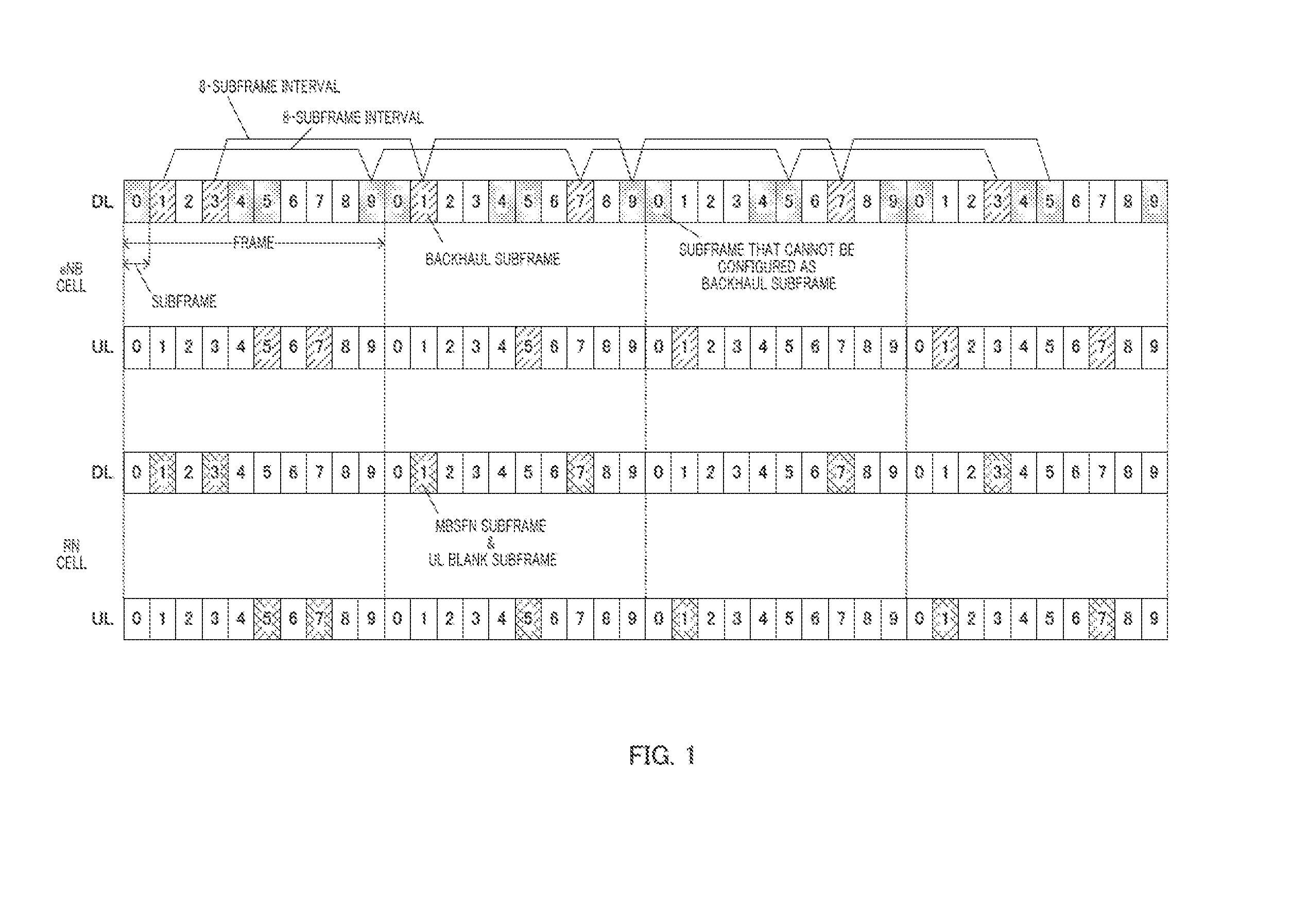
[0049]The communication system according to Embodiment 1 of the present invention includes base station 100, relay station 200 and a terminal. This communication system is, for example, an LTE-A system. Base station 100 is an LTE-A base station and communicates with relay station 200 through a backhaul.
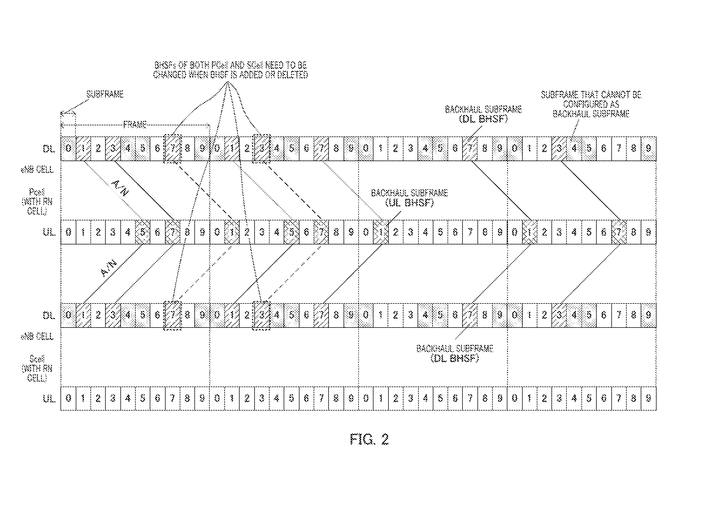
[0050]Furthermore, this communication system applies carrier aggregation to communication (backhaul communication) between base station 100 and relay station 200. That is, a plurality of CCs including a PCell and SCells are used for backhaul communication between base station 100 and relay station 200.
[0051]Furthermore, in this communication system, DL BHSFs of a PCell used for backhaul communication in downlink (DL) and UL BHSFs of the PCell used for backhaul communication in uplink (UL) are configured. Similarly, DL BHSFs of an SCell used for backhaul communication in downlink (DL) and UL BHSFs of the SCell used for backhaul communication in upli
embodiment 2
[0123]In Embodiment 2, when the base station configures DL BHSFs in an SCell at timings different from those of DL BHSFs of the PCell, the base station allocates PDSCH resources in the DL BHSFs of the SCell and also allocates PUSCH resources at the same time.
[0124]In base station 100 according to the present embodiment (FIG. 6), processing of control section 101, assignment section 104 and A / N receiving section 109 is partly different from that in Embodiment 1.
[0125]When configuring an A / N resource among PUCCH resources for each relay station 200, control section 101 configures the A / N resource using only a PUCCH of UL BHSFs configured in the PCell. That is, control section 101 does not configure any A / N resource using UL BHSFs configured in an SCell.
[0126]When allocating a PDSCH resource for each relay station 200, at a timing at which a DL BHSF is configured only in the SCell (timing different from that of a DL BHSF of the PCell), assignment section 104 also simultaneously al
embodiment 3
[0157]Embodiments 1 and 2 have been described with a case where a UL BHSF of an SCell is configured for each DL BHSF of the SCell transmitted at a timings different from that of a DL BHSFs of a PCell. In contrast, Embodiment 3 will be described with a case where UL BHSFs of the SCell are configured for every predetermined number of continuous DL BHSFs of the SCell transmitted at timings different from those of DL BHSFs of the PCell.
[0158]In base station 100 according to the present embodiment (FIG. 6), processing of control section 101 and A / N receiving section 109 is partly different from Embodiment 1.
[0159]When configuring A / N resources in PUCCH resources for each relay station 200, control section 101 configures one BHSF (A / N resource) of the SCell for every predetermined number of continuous DL BHSFs of the SCell transmitted at timings different from those of DL BHSFs of the PCell among DL BHSFs configured in the downlink of the SCell. For example, control section 101 configu
PUM
 Abstract
Description
Claims
Application Information
 - R&D Engineer
- R&D Manager
- IP Professional
- Industry Leading Data Capabilities
- Powerful AI technology
- Patent DNA Extraction
Browse by: Latest US Patents, China's latest patents, Technical Efficacy Thesaurus, Application Domain, Technology Topic.
© 2024 PatSnap. All rights reserved.Legal|Privacy policy|Modern Slavery Act Transparency Statement|Sitemap