Low Profile Compressor Bleed Air-Oil Coolers

a compressor and air-oil cooler technology, applied in the direction of machines/engines, efficient propulsion technologies, mechanical equipment, etc., can solve the problems of affecting the design of small core engines, affecting the overall thrust output of the engine, and adding undesirable weight to the small core engin

Active Publication Date: 2014-04-10
RAYTHEON TECH CORP
View PDF15 Cites 18 Cited by
  • Summary
  • Abstract
  • Description
  • Claims
  • Application Information

AI Technical Summary

Benefits of technology

This patent describes an air-oil cooling system used in a gas turbine engine that includes a fan, a low pressure compressor, a low pressure compressor panel, and a V-groove. It also has multiple heat exchangers between them. These components are designed to efficiently transfer thermal energy from the high temperature gases produced by the engine's rotating blades into lower temperatures before being released back into the atmosphere.

Problems solved by technology

Gas turbine engines require efficient lubrication and cooling of certain parts like bearings and gearboxes due to their high work load compared to traditional engines. However, this requires more space within the engine itself, making it difficult to fit these parts properly. Therefore, there is a technical problem addressed in this patent text where the goal is to develop an improved AOC that can effectively cool the oil while maintaining its effectiveness over existing designs.

Method used


Image

  • Low Profile Compressor Bleed Air-Oil Coolers
  • Low Profile Compressor Bleed Air-Oil Coolers
  • Low Profile Compressor Bleed Air-Oil Coolers

Examples


Embodiment Construction

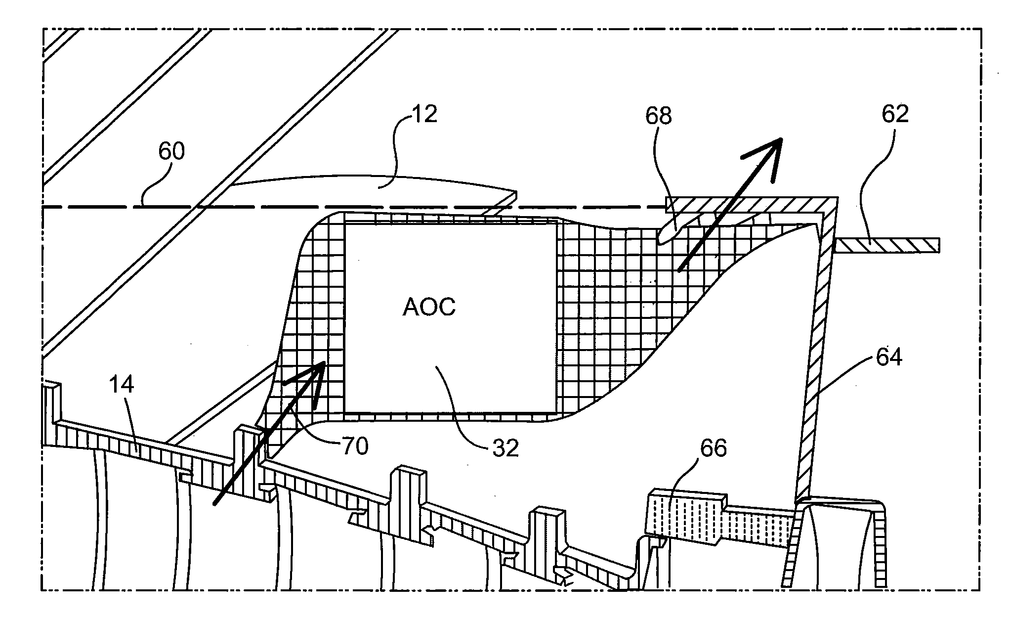
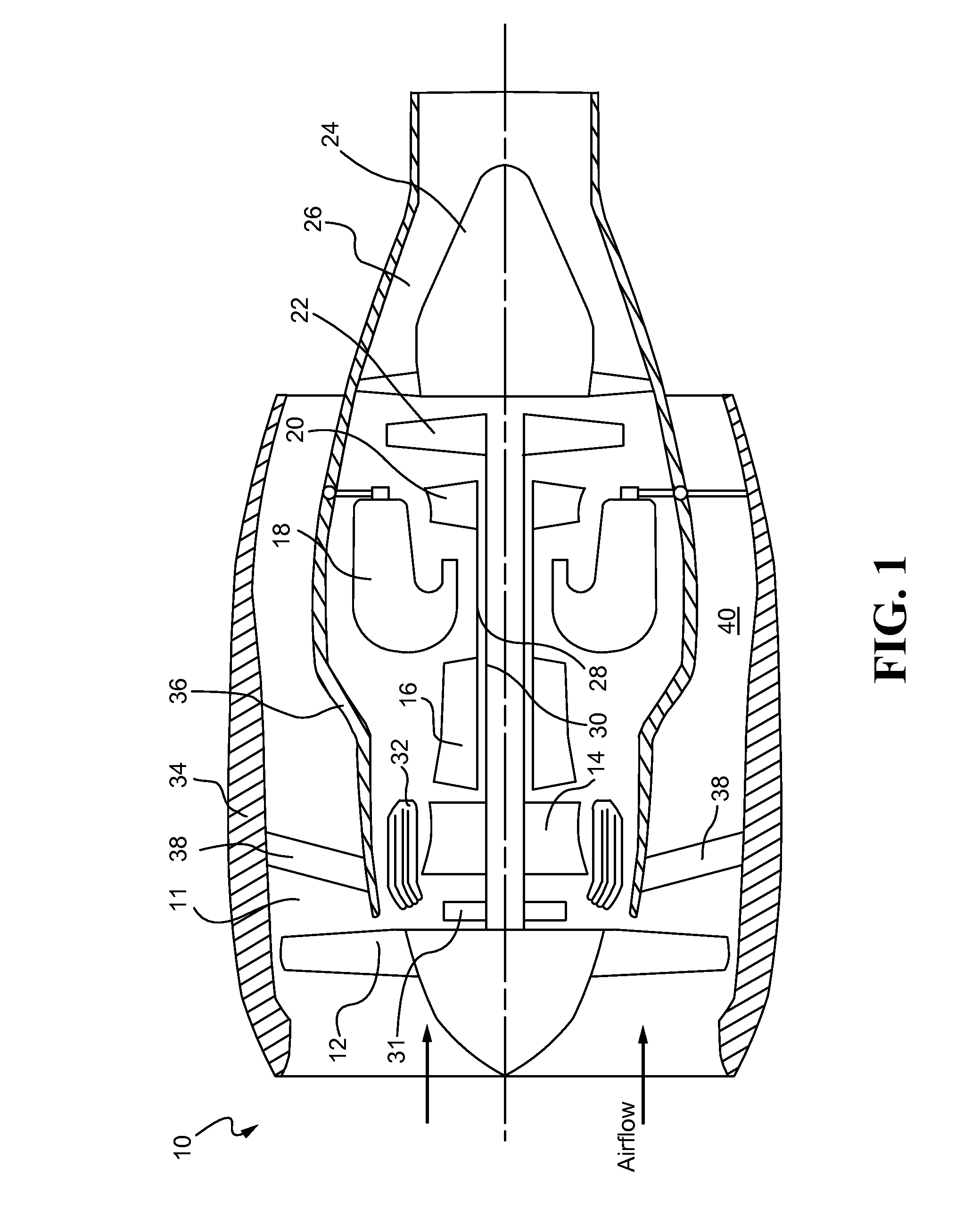
[0033]Referring now to the drawings, and with specific reference to FIG. 1, there is depicted an exemplary gas turbine 10 wherein various embodiments of the present disclosure may be utilized. In this example, the industrial gas turbine 10 may include a compressor section 11 which may comprise, sequentially from the forefront of the gas turbine engine 10, a fan 12, a low pressure compressor 14, a high pressure compressor 16, a combustor chamber 18 downstream of the compressor section 11, a high pressure turbine 20 and a low pressure turbine 22 both downstream of the combustor chamber 18, a tail cone 24, and an exhaust nozzle 26. Further, a high pressure shaft 28 may couple the high pressure compressor 16 with the high pressure turbine 20; while a low pressure shaft 30 may couple the low pressure compressor 14 with the low pressure turbine 22. Both shafts 28 and 30 may be rotatable about an axis A. The low pressure shaft 30 may drive the fan 12 through a gear train 31. There may be a lo


PUM


Abstract

An air-oil cooler (AOC) for a gas turbine engine is disclosed. The AOC may comprise an oil inlet, an oil outlet, and heat exchange elements between the oil inlet and the oil outlet. The AOC may be longitudinally positioned between a fan and a V-groove of the engine and radially spaced between a low pressure compressor and a low pressure compressor panel. A gas turbine engine comprising an AOC is disclosed. The AOC of the engine may comprise an oil inlet, an oil outlet, and heat exchange elements between the oil inlet and the oil outlet. The AOC of the engine may be longitudinally positioned between a fan and a V-groove of the engine and radially spaced between a low pressure compressor and a low pressure compressor panel. A method of operating an AOC for use on a gas turbine engine is also disclosed.

Description


Claims


Application Information

Patent Timeline
Owner RAYTHEON TECH CORP
Why Eureka
Try Eureka