Setting tool

Active Publication Date: 2014-11-13
WELLTEC AS
View PDF4 Cites 1 Cited by
  • Summary
  • Abstract
  • Description
  • Claims
  • Application Information

AI Technical Summary

Benefits of technology

[0004]It is an object of the present invention to wholly or partly overcome the above disadvantages and drawbacks of the prior art. More specifically, it is an object to provide an improved setting tool that may be released from a downhole object, such as a running tool or a plug in case of a malfunction in the mechanical- and/or hydraulic system of the plug or setting tool, so that the setting tool does not get stuck downhole.

Problems solved by technology

However, if the setting process fails, e.g. due to malfunction of the mechanical system of the plug or setting tool, the plug may not be appropriately set, whereby the setting tool is not released from the plug.
In case of connection to a partly set plug, it may be very difficult, or simply impossible, to extract the setting tool from the well, and then special tools are required.
In order to retrieve a stuck tool, more heavy equipment having more power is necessary to pull the tool out, or if the stuck setting tool remains stuck, the tool has to be drilled out, resulting in costly production time being lost.

Method used


Image

  • Setting tool
  • Setting tool
  • Setting tool

Examples


Example

[0069]All the figures are highly schematic and not necessarily to scale, and they show only those parts which are necessary in order to elucidate the invention, other parts being omitted or merely suggested.

DETAILED DESCRIPTION OF THE INVENTION

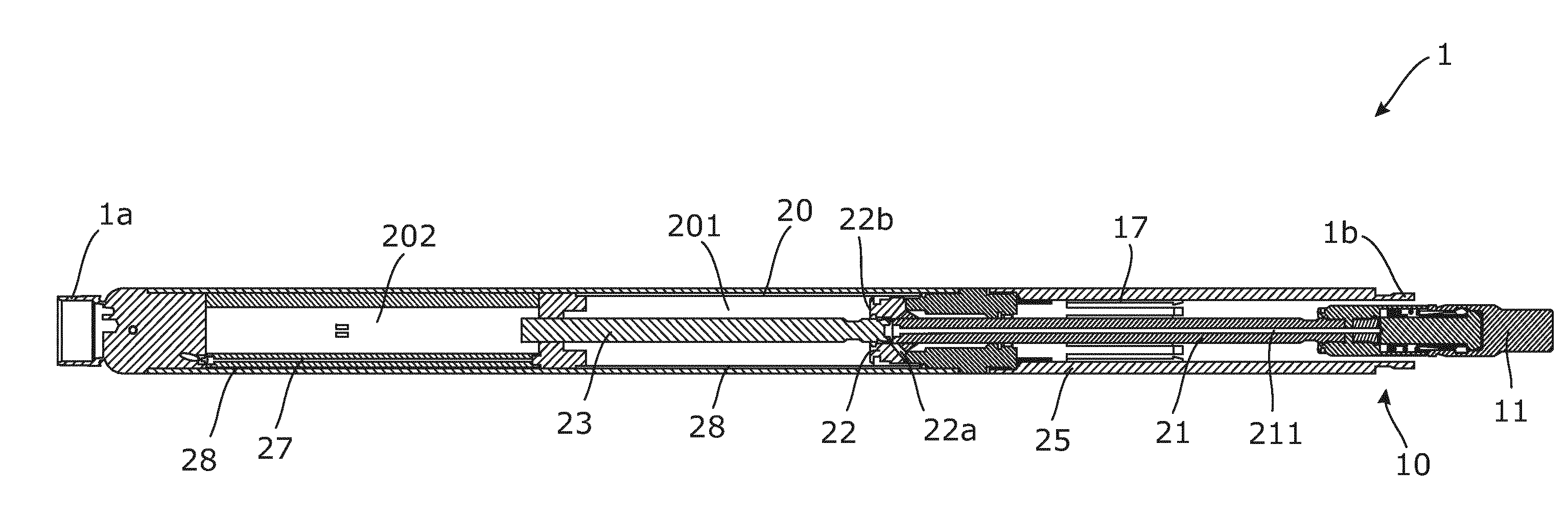
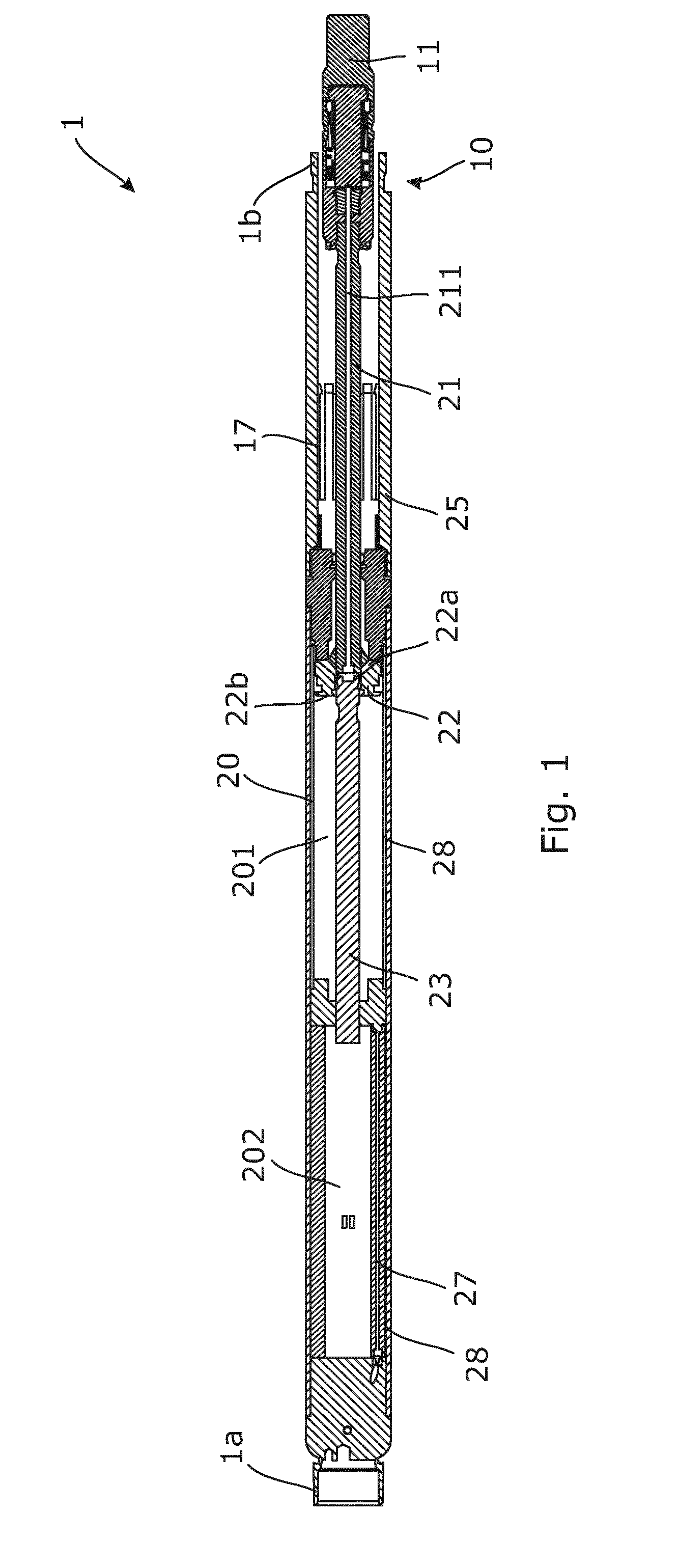
[0070]FIG. 1 shows a downhole setting tool 1 extending between a proximal end 1a and a distal end 1b. The proximal end 1a constitutes an interface to the remaining tool string, and the distal end 1b faces the object 80 to be set during use, as shown in FIG. 4. The downhole setting tool 1 comprises a stroke cylinder 20 constituting most of the longitudinal extension of the downhole setting tool 1 and a spacer element 25 extending from the stroke cylinder 20 towards the distal end 1b of the downhole setting tool 1. The stroke cylinder 20 defines a piston chamber 201 in which a hydraulic piston 22 is slidably arranged and movable between a downstroke position, wherein the hydraulic piston 22 is pushed all the way towards the distal end 1b of the dow


PUM


Abstract

The present invention relates to a release device (10) for releasably connecting a downhole object (80), such as a running tool or a plug, to a setting tool, the release device extending between a proximal end (10a) adapted to be coupled to the setting tool and a distal end (10b) adapted to be coupled to the downhole object, the release device comprising a base element (16) extending in a longitudinal direction and a connecting element arranged in continuation of the base element, the connecting element (11) constituting the distal end of the release device and being adapted to be coupled to the downhole object, wherein the connecting element is releasably coupled to the base element by an activatable release mechanism (60). Further, the invention relates to a downhole setting tool for setting an object in a wellbore and to a method for disconnecting a downhole object.

Description


Claims


Application Information

Patent Timeline
Owner WELLTEC AS
Why Eureka
Try Eureka