Cold wind generation from slag heat

a technology of slag heat and cold wind, which is applied in the direction of furnaces, lighting and heating apparatus, machines/engines, etc., can solve the problems of large cosub>2 /sub>emission of conversion of carbon compounds, and very largely lost sensible heat of blast furnace gas, etc., to save external energy, simplify operation, and reduce costs

Inactive Publication Date: 2014-12-04
PAUL WURTH SA
View PDF14 Cites 2 Cited by
  • Summary
  • Abstract
  • Description
  • Claims
  • Application Information

AI Technical Summary

Benefits of technology

The technical effect described by this patented technology relates to improving the performance of coolers during iron making processes through efficient usage of waste heat generated when burning off coke or producing steam without converting them into other forms like electricity. By recovering thermal energy from the melting process itself, these techniques save on external resources while still providing more useful results than traditional methods.

Problems solved by technology

This technical problem addressed in this patents relates to improving the efficiency of producing useful chemical substances such as hydrocarbons through reduction of greenhouse gases during production processes without losing valuable resources due to wasted energy sources associated therewith.

Method used


Image

  • Cold wind generation from slag heat
  • Cold wind generation from slag heat

Examples


Embodiment Construction

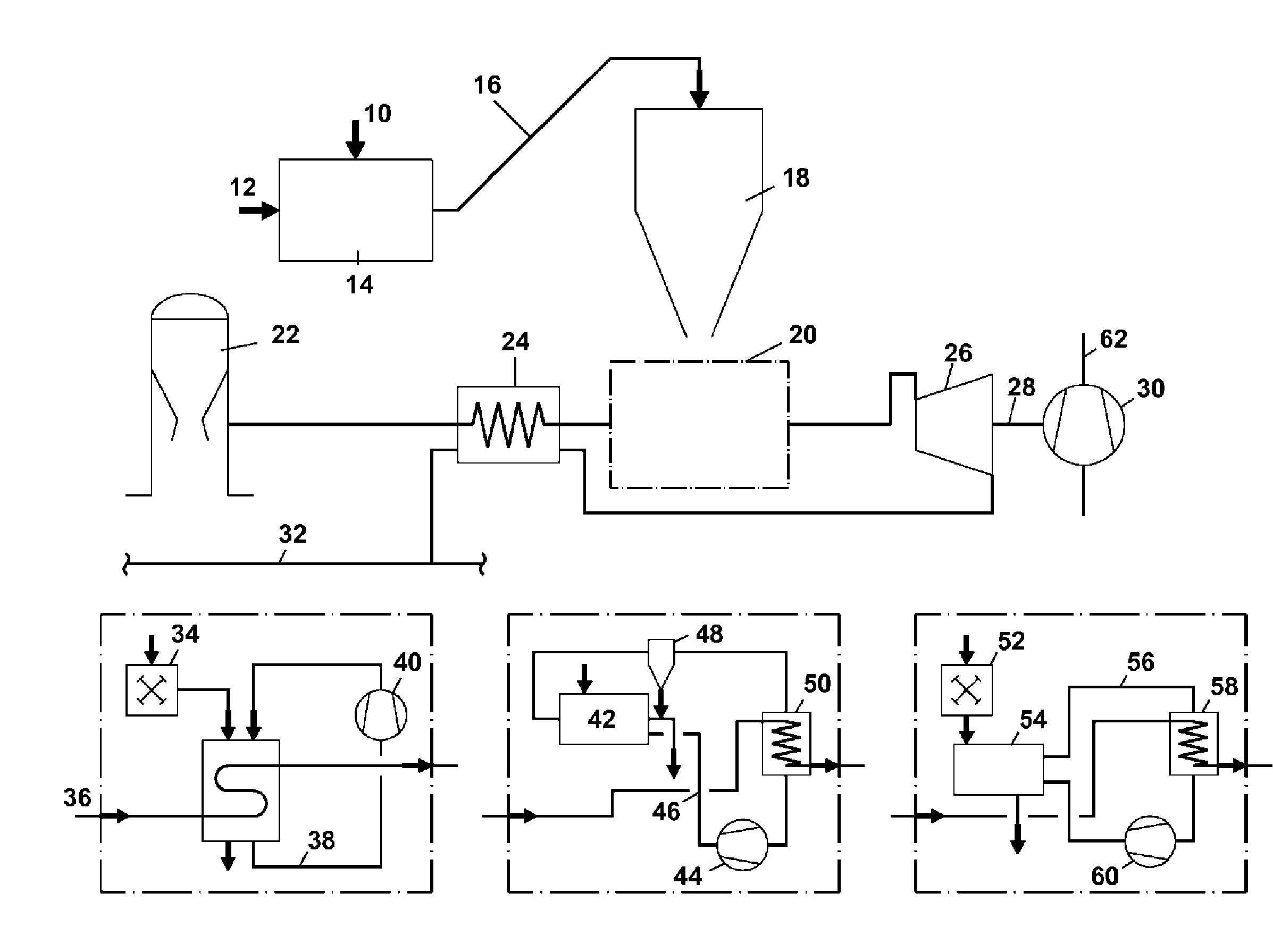
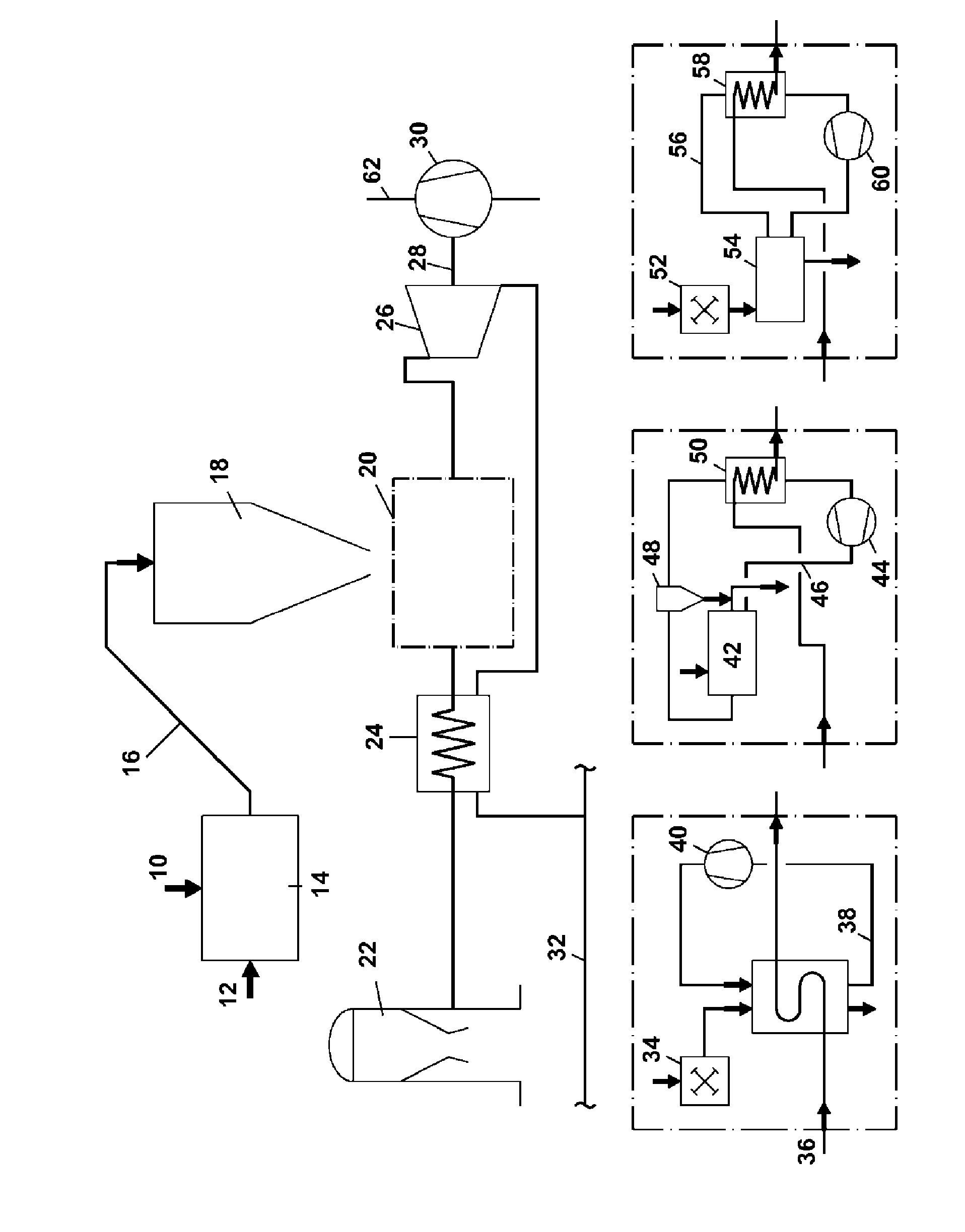
[0040]Various embodiments of this heat recovery and use for generating cold-air blast are explained below with reference to FIG. 1:

[0041]The liquid, hot slag 10 which is obtained periodically during each tapping operation is cooled by introduction of a cold solid 12 in a granulation installation 14 and solidifies, wherein the resultant hot solids mixture still has the highest possible temperature which is substantially limited by the subsequent processing of the mixture.

[0042]Cold, vitreously solidified blast furnace slag may, for example, be used as the cold solid. Using cold blast furnace slag has the advantage that, after the introduction thereof into the liquid slag, a homogeneous hot solids mixture is obtained.

[0043]Additionally or alternatively, however, spherical or similarly shaped metal bodies, preferably of iron or steel, may also be used as the cold solid. On introduction into the liquid slag, the metal bodies bring about more rapid solidification of the liquid slag and so i


PUM

PropertyMeasurementUnit
Temperatureaaaaaaaaaa

Abstract

The present invention describes a method for generating cold-air blast from slag heat, wherein the method comprises the following steps: a. providing hot, granulated slag, b. providing wet blast furnace gas, c. preheating the wet blast furnace gas, whereby preheated blast furnace gas is obtained, d. transferring heat from the hot, granulated slag to the preheated blast furnace gas, wherein hot blast furnace gas is obtained, e. expanding the hot blast furnace gas in a turbine, wherein energy is released and expanded blast furnace gas is obtained, f. using the released energy to drive a cold-air blast compressor for compressing the cold-air blast, wherein a shaft is driven by expansion of the hot blast furnace gas in a turbine, wherein said shaft drives the cold-air blast compressor and wherein the expanded blast furnace gas is used for preheating the wet blast furnace gas, whereby cold, expanded blast furnace gas is obtained.

Description


Claims


Application Information

Patent Timeline
Owner PAUL WURTH SA
Why Eureka
Try Eureka