Apparatus for coupling prosthetic components having angular and translational offset

a technology of prosthetic components and accessories, applied in the field of accessories for coupling prosthetic components, can solve the problems of limiting the available offset of prosthetic components and the limitation of components that can only be offs

Inactive Publication Date: 2015-01-08
MEDEX INT
View PDF8 Cites 32 Cited by
  • Summary
  • Abstract
  • Description
  • Claims
  • Application Information

AI Technical Summary

Benefits of technology

This patented technology allows two parts (a part called an implant) move with each other when they're used on joints such as knees or legs. They also have curled channels inside them where there connectors like rods. By moving these parts backwardly and forth along their curved paths, it becomes possible to change how well this connection works between the bone ends and muscles around them.

Problems solved by technology

There exist needs for better ways to attach prosthesis parts with greater flexibility than current designs due to their fixed connection points on either side of the part's residue bone. Existing methods require multiple steps involving trial-and-error fitting each joint separately before attaching them properly. Therefore, this patented technology provides technical solutions for improving these capabilities without requiring complicated assembly procedures.

Method used


Image

  • Apparatus for coupling prosthetic components having angular and translational offset
  • Apparatus for coupling prosthetic components having angular and translational offset
  • Apparatus for coupling prosthetic components having angular and translational offset

Examples


second embodiment

[0068]Referring now to FIGS. 10-12B, a prosthetic coupling apparatus 1000A according to the present invention is illustrated. The prosthetic coupling apparatus 1000A is identical to the prosthetic coupling apparatus 1000 discussed above with the exception that the pyramid block 203 of the second component 200 has been replaced with a pyramid block receiving cavity 230A. All features of the prosthetic coupling apparatus 1000 are applicable to the prosthetic coupling apparatus 1000A except that the pyramid block 203 has been changed to the pyramid receiving cavity 203A. Thus, the description of the features and components of the prosthetic coupling apparatus 1000 that are also present in the prosthetic coupling apparatus 1000A (whether marked with a reference numeral or not) is applicable to the prosthetic coupling apparatus 1000A. The details with regard to the contours and curvatures of the various surfaces of the prosthetic coupling apparatus 1000A are not described herein, it being u

third embodiment

[0072]Referring now to FIGS. 13, a prosthetic coupling apparatus 1000B according to the present invention is illustrated. The prosthetic coupling apparatus 1000B is identical to the prosthetic coupling apparatus 1000 discussed above with the exception that the pyramid block 203 has been replaced with a pyramid receiver 203A similar to that discussed above in FIGS. 10-12 with regard to the prosthetic coupling apparatus 1000A and the hub 103 has been replaced with a pyramid block receiving cavity 103B. Thus, all features of the prosthetic coupling apparatus 1000 are applicable to the prosthetic coupling apparatus 1000B except that the pyramid block 203 has been changed to the pyramid block receiving cavity 203B and the hub 103 has been replaced with the pyramid block receiving cavity 103B. Thus, the description of the features and components of the prosthetic coupling apparatus 1000 that are also present in the prosthetic coupling apparatus 1000B (whether marked with a reference numeral


PUM


Abstract

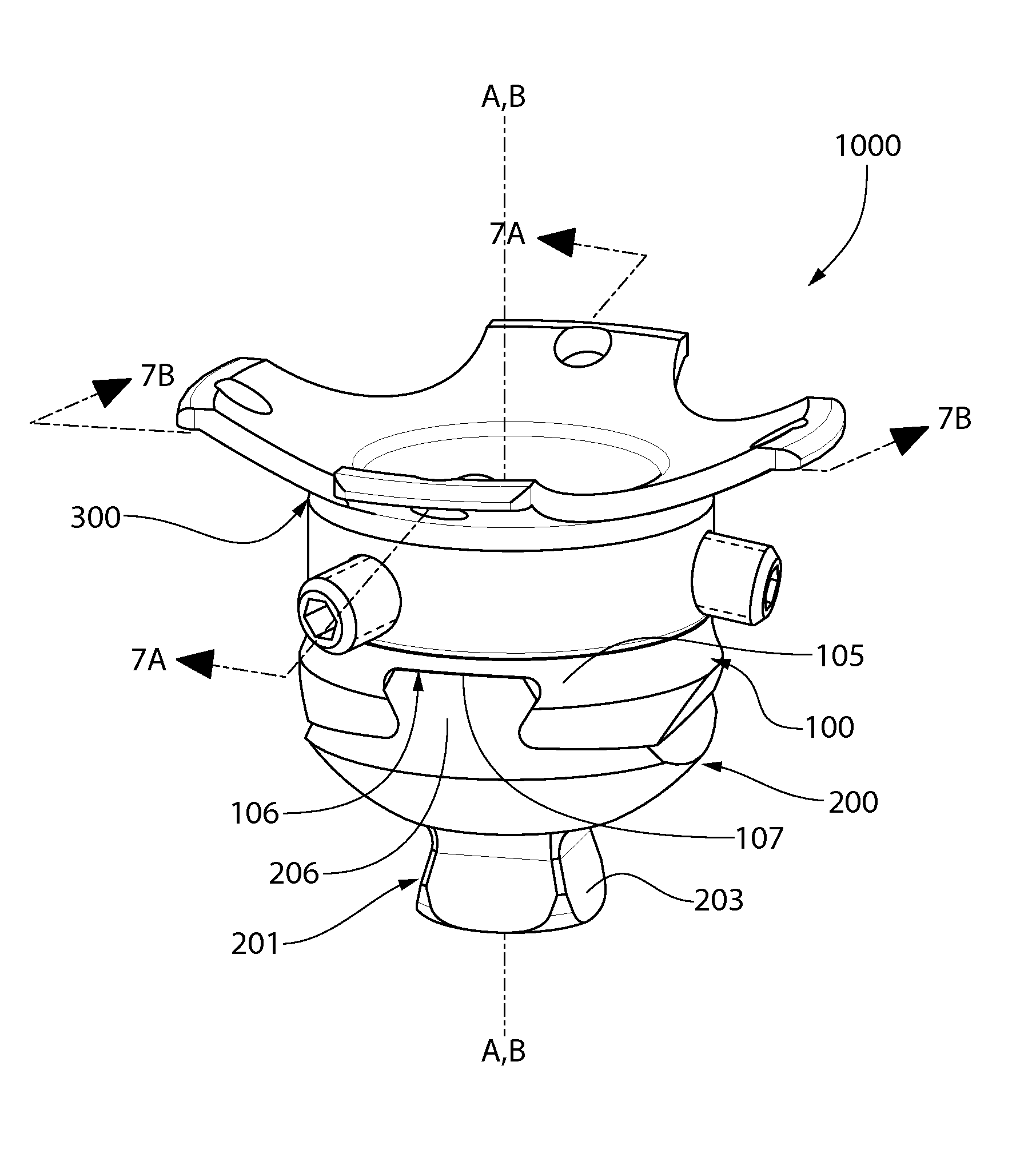
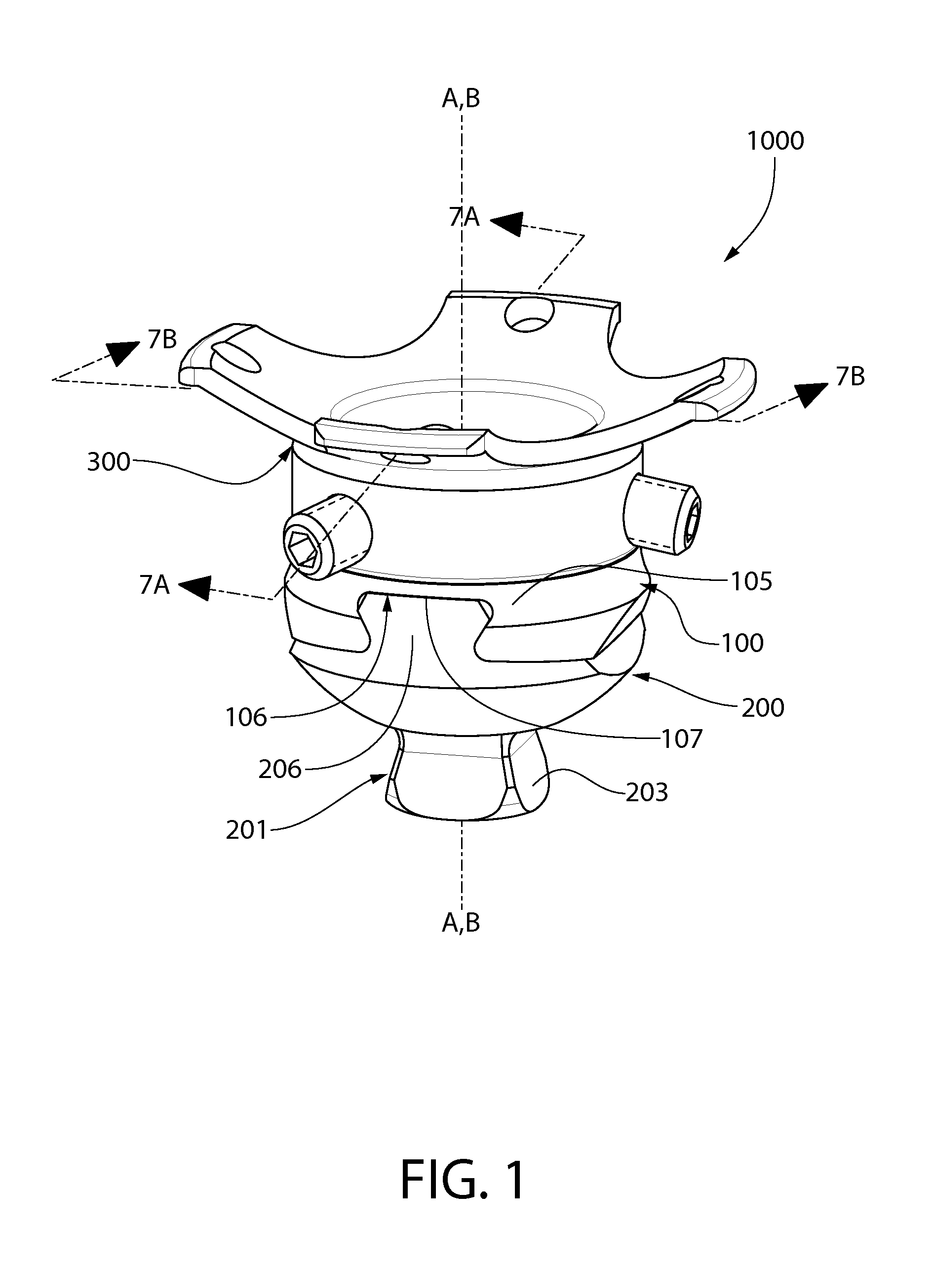
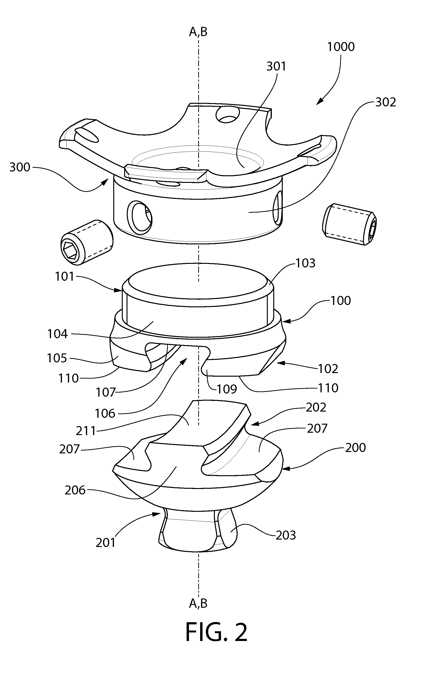
An prosthetic alignment device. In one embodiment, the prosthetic alignment device includes a first component having a first end portion configured to be coupled to one of a prosthesis or a residual limb and a second end portion having a curved channel extending along a curved channel axis; a second component extending along a second central axis comprising a first end portion configured to be coupled to the other one of the prosthesis or the residual limb and a second end portion comprising a curved bar that extends along a curved bar axis, the curved bar positioned within the curved channel so as to be slidable along the curved channel axis in first and second opposite directions so that the first and second components can be selectively adjusted to a plurality of relative positions.

Description


Claims


Application Information

Patent Timeline
Owner MEDEX INT
Why Eureka
Try Eureka