Modular power conversion system and method

Inactive Publication Date: 2015-05-28
SOLANTRO SEMICON CORP
View PDF3 Cites 16 Cited by
  • Summary
  • Abstract
  • Description
  • Claims
  • Application Information

AI Technical Summary

Benefits of technology

[0009]In view of the foregoing, an embodiment herein provides a method for converting electrical power, the method comprising providing a modular power converter comprising a mode control module and a plurality of autonomously operating power conversion modules operatively connected to a first power bus; selecting, by the mode control module, individual modes of operation for the plurality of power conversion modules to meet a power conversion requirement; receiving electrical power of a first power type from the first power bus by at least one of the power conversion modules; and converting the received electrical power into electrical power of a second power type by the at least one power conversion module. The plurality of power conversion modules comprise may substantially equal volts-amperes-reactive conversion capacities, and wherein the selecting of individual modes of operation comprises selecting the power conversion modules to operate in either a standby mode or one of an inductive or a capacitive mode so that reactive power is either absorbed or supplied to the first power bus. The power conversion modules operating in one of the inductive or capacitive mode all convert substantially the same volts-amperes-reactive (VAr) amounts.

Problems solved by technology

If there is a large capacitive load, the VAr compensator could consume reactive power to correct the power factor closer to unity.
In known modular power converters, the modules are typically not autonomous and do not perform the complete power conversion function of the power converter.

Method used


Image

  • Modular power conversion system and method
  • Modular power conversion system and method
  • Modular power conversion system and method

Examples


Example

[0045]The embodiments herein and the various features and advantageous details thereof are explained more fully with reference to the non-limiting embodiments that are illustrated in the accompanying drawings and detailed in the following description. Descriptions of well-known components and processing techniques are omitted so as to not unnecessarily obscure the embodiments herein. The examples used herein are intended merely to facilitate an understanding of ways in which the embodiments herein may be practiced and to further enable those of skill in the art to practice the embodiments herein. Accordingly, the examples should not be construed as limiting the scope of the embodiments herein.

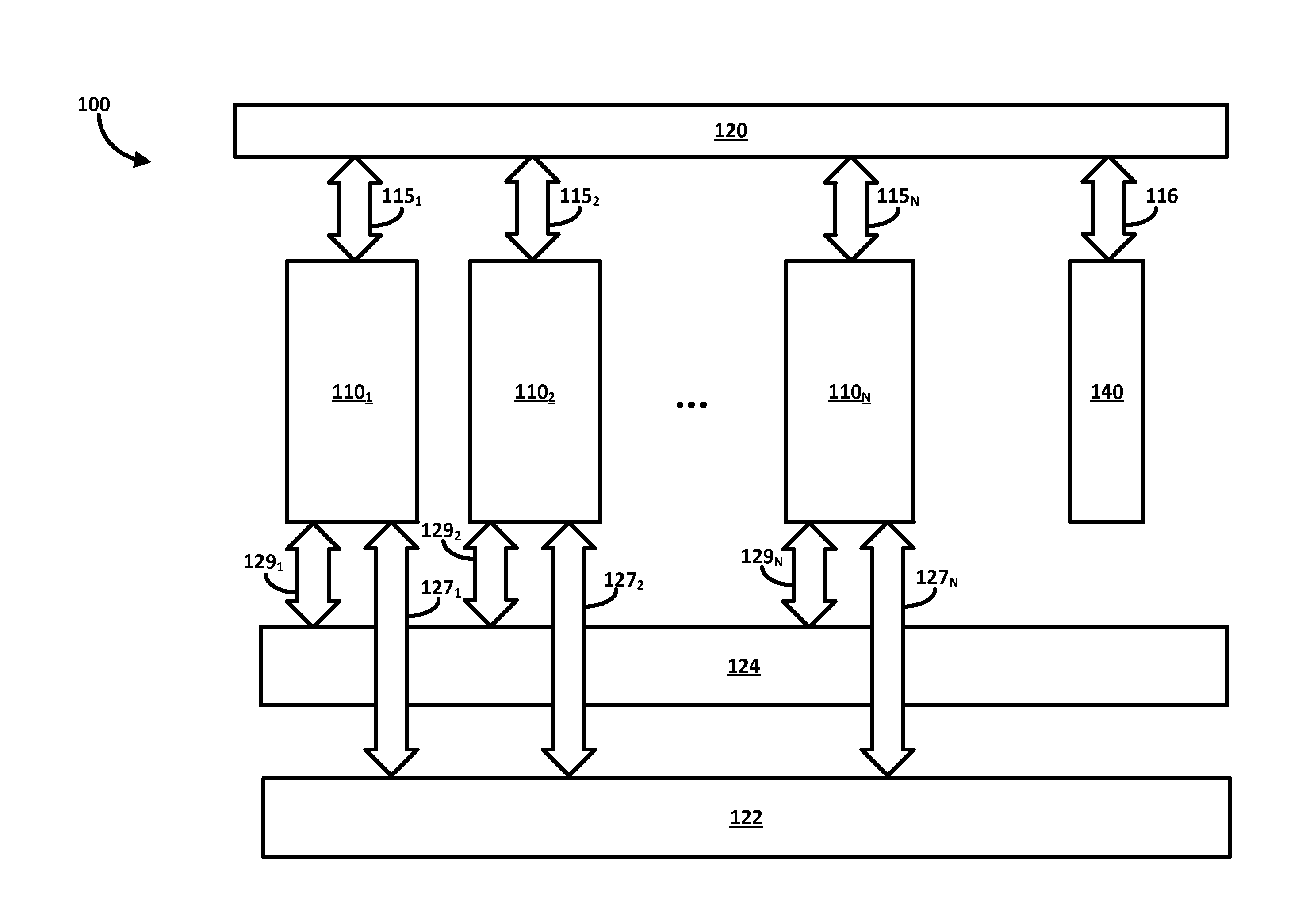
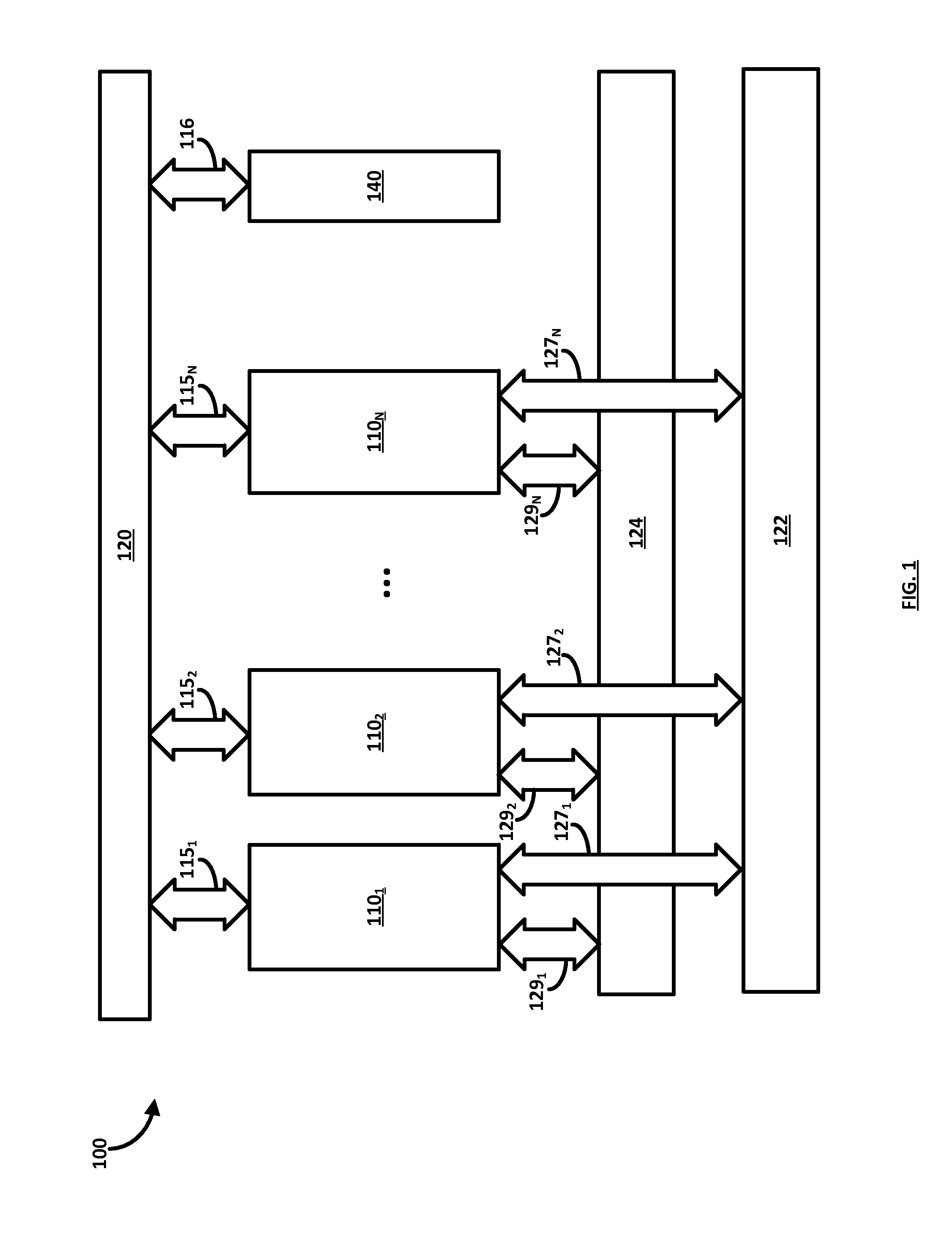
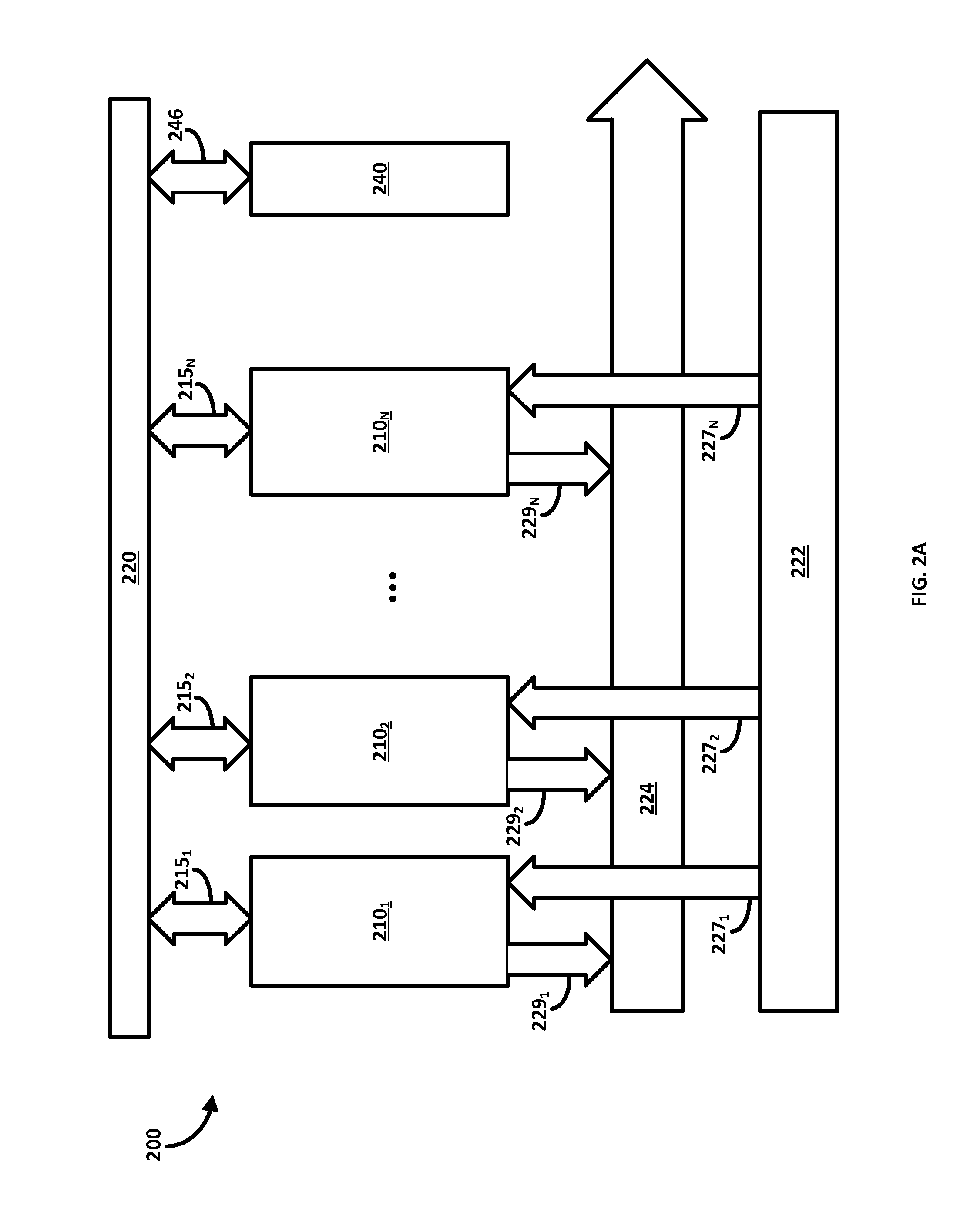
[0046]The embodiments herein provide a modular power converter operating a plurality of power conversion modules. Referring now to the drawings, and more particularly to FIGS. 1 through 12, where similar reference characters denote corresponding features consistently throughout the figures, there


PUM


Abstract

A method for converting electrical power includes providing a modular power converter having a mode control module and a plurality of autonomously operating power conversion modules operatively connected to a first power bus; selecting, by the mode control module, individual modes of operation for the plurality of power conversion modules to meet a power conversion requirement; receiving electrical power of a first power type from the first power bus by at least one of the power conversion modules; and converting the received electrical power into electrical power of a second power type by the at least one power conversion module.

Description


Claims


Application Information

Patent Timeline
Owner SOLANTRO SEMICON CORP
Why Eureka
Try Eureka