Circularly polarizing plate, method for manufacturing same, and optical laminate
- Summary
- Abstract
- Description
- Claims
- Application Information
AI Technical Summary
Benefits of technology
Problems solved by technology
Method used
Image

Examples
first embodiment
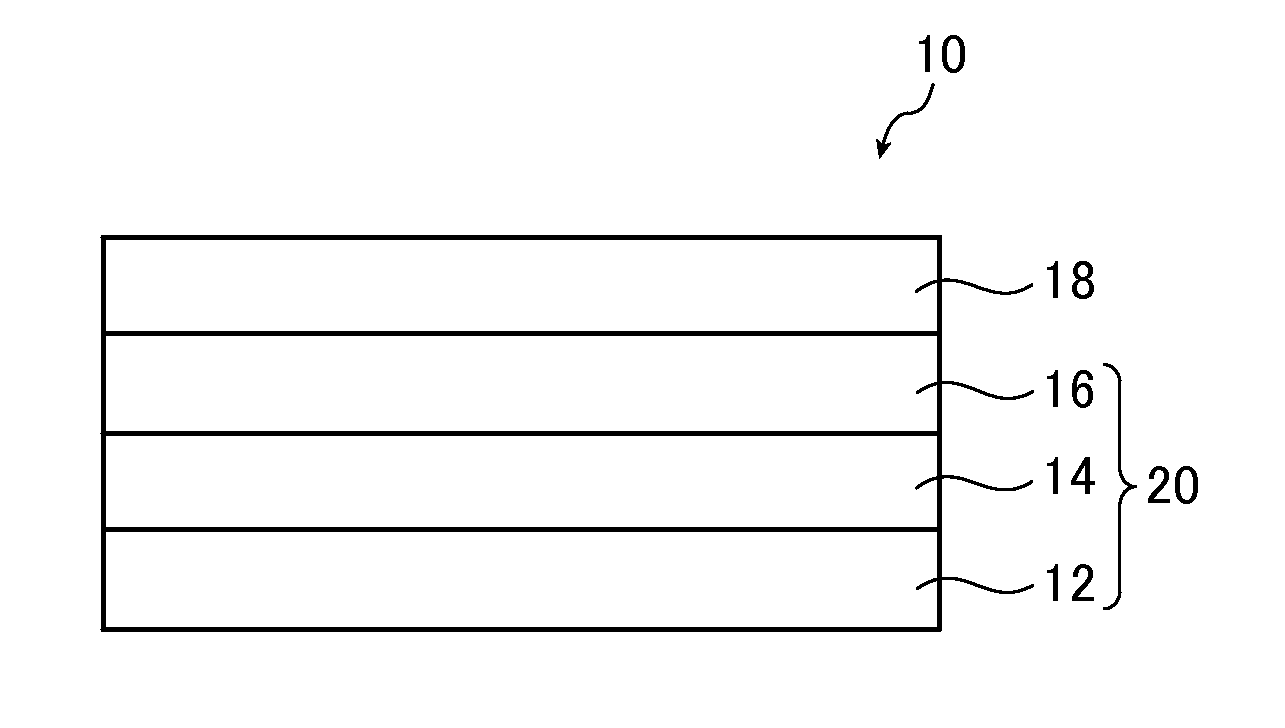
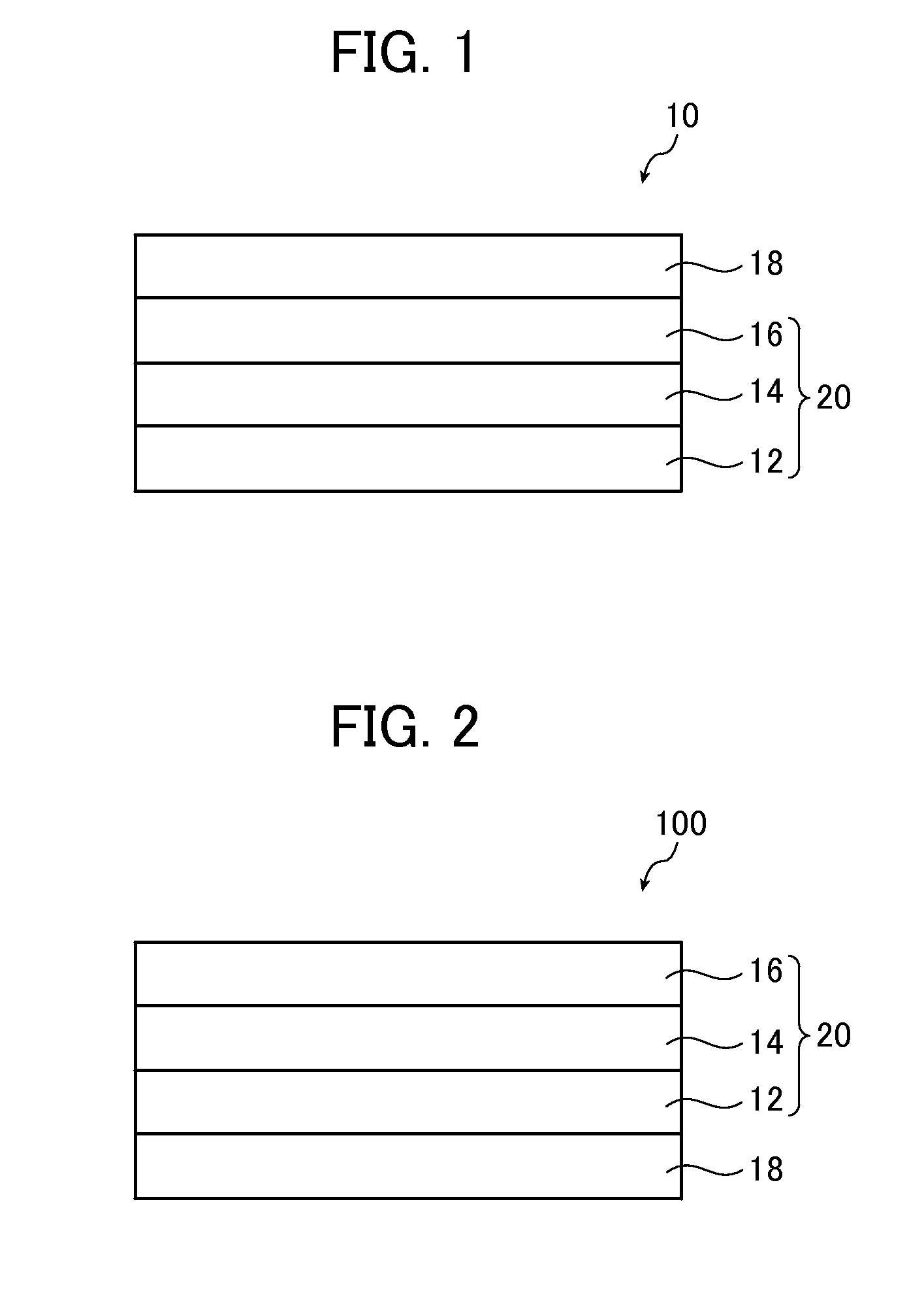
[0027]Hereinafter, a first embodiment of a circularly polarizing plate of the present invention will be described with reference to a drawing. FIG. 1 is a schematic cross-sectional view of the first embodiment of the circularly polarizing plate of the present invention.
[0028]A circularly polarizing plate 10 includes a transparent support 12, an optically anisotropic layer A14, an optically anisotropic layer B16, and a polarizing film 18 that are laminated on each other in this order. The optically anisotropic layer A14 is formed of a composition containing a discotic liquid crystal compound having a polymerizable group, and the optically anisotropic layer B16 is formed of a composition containing a rod-like liquid crystal compound having a polymerizable group. The transparent support 12, the optically anisotropic layer A14, and the optically anisotropic layer B16 constitute an optical laminate 20.
[0029]Hereinafter, each of the members will be specifically described.
[0030]
[0031]The tran
second embodiment
[0247]Hereinafter, a second embodiment of the circularly polarizing plate of the present invention will be described with reference to a drawing. FIG. 2 is a schematic cross-sectional view of the second embodiment of the circularly polarizing plate of the present invention.
[0248]A circularly polarizing plate 100 includes a polarizing film 18, a transparent support 12, an optically anisotropic layer A14, and an optically anisotropic layer B16 that are laminated on each other in this order. The angular relationship between the absorption axis of the polarizing film 18, the slow axis of the optically anisotropic layer A14, and the slow axis of the optically anisotropic layer B16 is not particularly limited, and for example, the angular relationship of the aforementioned first embodiment is established therebetween. For instance, when one of the optically anisotropic layer A and the optically anisotropic layer B is a λ / 4 film, and the other is a λ / 2 film, it is preferable that an angle
example 1
Preparation of Transparent Support A
[0252]The following composition was put into a mixing tank and stirred while being heated such that the respective components were dissolved, thereby preparing a cellulose acylate solution A.
Composition of cellulose acylate solution ACellulose acetate with a degree of100 parts by masssubstitution of 2.86Triphenyl phosphate (plasticizer) 7.8 parts by massBiphenyl diphenyl phosphate 3.9 parts by mass(plasticizer)Methylene chloride (first solvent)300 parts by massMethanol (second solvent) 54 parts by mass1-Butanol 11 parts by mass
[0253]The following composition was put into another mixing tank and stirred while being heated such that the respective components were dissolved, thereby preparing an additive solution B.
Composition of additive solution BThe following compound B1 (Re reducing40 parts by massagent)The following compound B2 (wavelength 4 parts by massdispersion control agent)Methylene chloride (first solvent)80 parts by massMethanol (second sol
PUM
| Property | Measurement | Unit |
|---|---|---|
| Angle | aaaaa | aaaaa |
| Nanoscale particle size | aaaaa | aaaaa |
| Nanoscale particle size | aaaaa | aaaaa |
Abstract
Description
Claims
Application Information
 - R&D Engineer
- R&D Manager
- IP Professional
- Industry Leading Data Capabilities
- Powerful AI technology
- Patent DNA Extraction
Browse by: Latest US Patents, China's latest patents, Technical Efficacy Thesaurus, Application Domain, Technology Topic.
© 2024 PatSnap. All rights reserved.Legal|Privacy policy|Modern Slavery Act Transparency Statement|Sitemap