Flowpack Tray

a technology of flowpack and tray, which is applied in the direction of liquid handling, closure using stoppers, caps, etc., can solve the problems of limiting the performance of the tray, the complexity and cost of depositing such layers on three-dimensional structures, and the inability to thermoform without losing the barrier properties, etc. problem, to achieve the effect of limiting the use of such layers to very specific applications

Active Publication Date: 2015-09-10
AMCOR FLEXIBLE KREUZLINGEN LTD
View PDF8 Cites 0 Cited by
  • Summary
  • Abstract
  • Description
  • Claims
  • Application Information

AI Technical Summary

Benefits of technology

The present invention relates to a new type of packaging that can be used for storing liquids. This package consists of two layers: an outer layer made from plastic material with a hole on it called a tray, which holds liquid inside. A cover is then placed over this tray. When needed, the cover is removed by pulling it upwardly through the holes in the tray.

Problems solved by technology

This patent describes a problem with current packaging materials used for storing products like foodstuffs. These materials have limited effectiveness due to factors like poor barrier properties, difficulty in depositing coatings onto complex shapes, and difficulties in printing large surface areas. Additionally, there may be environmental concerns associated with disposal of these packaged items after use.

Method used


Image

  • Flowpack Tray
  • Flowpack Tray
  • Flowpack Tray

Examples


Embodiment Construction

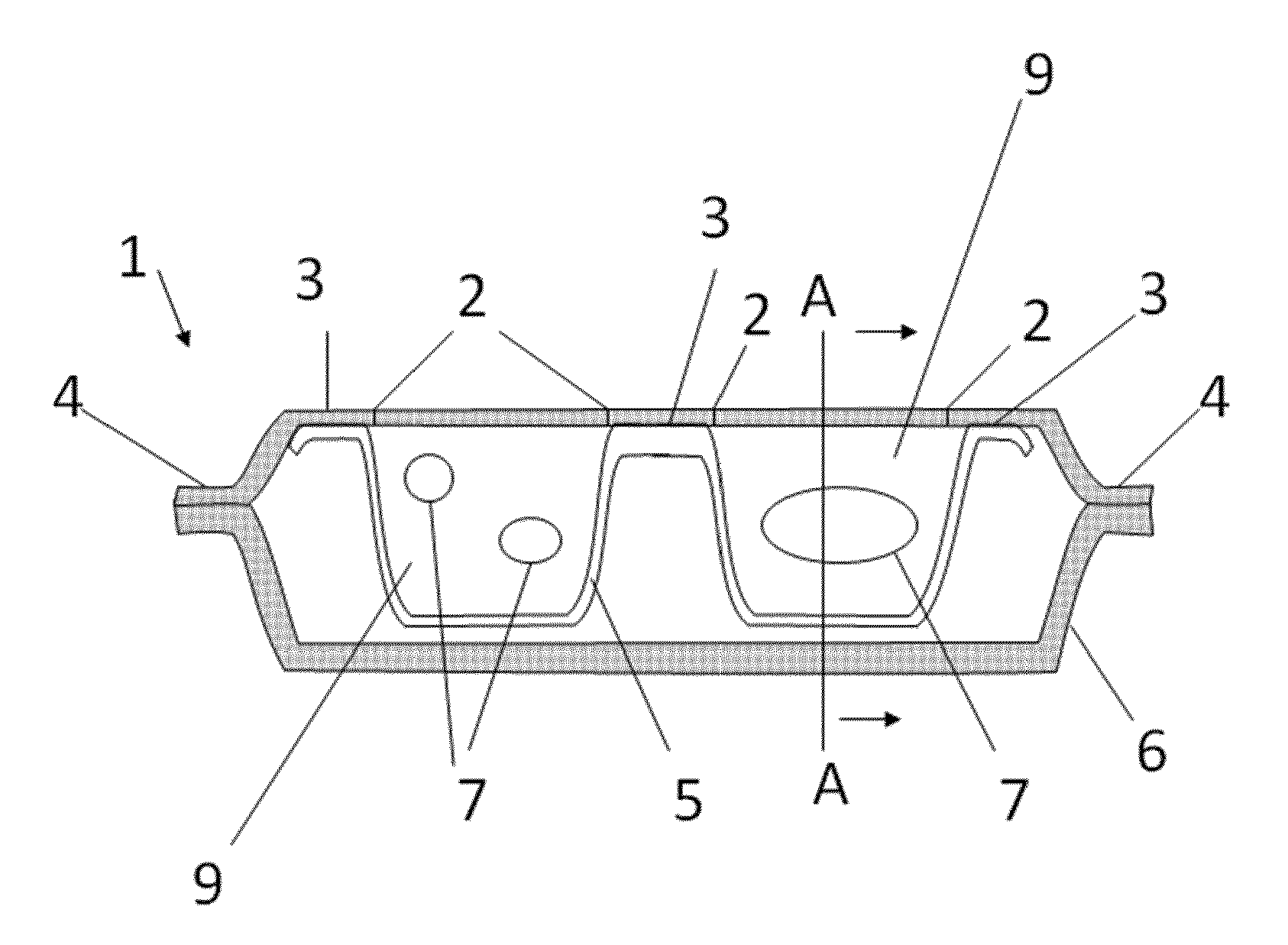
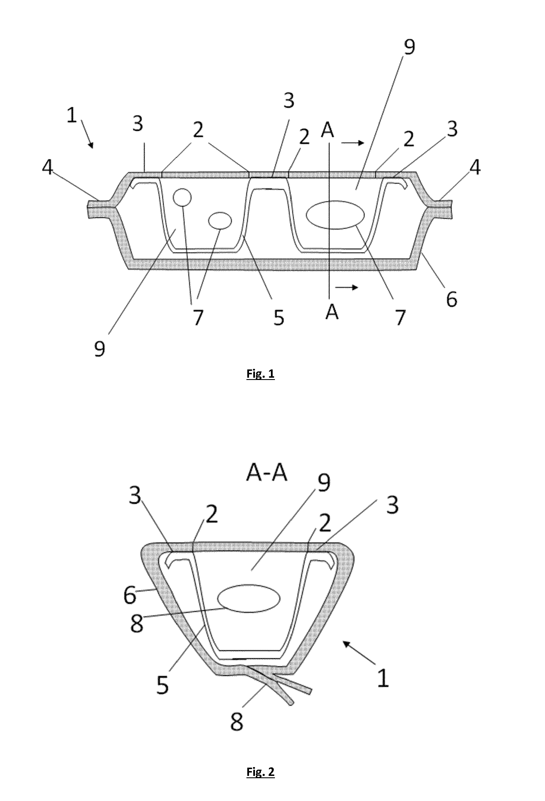
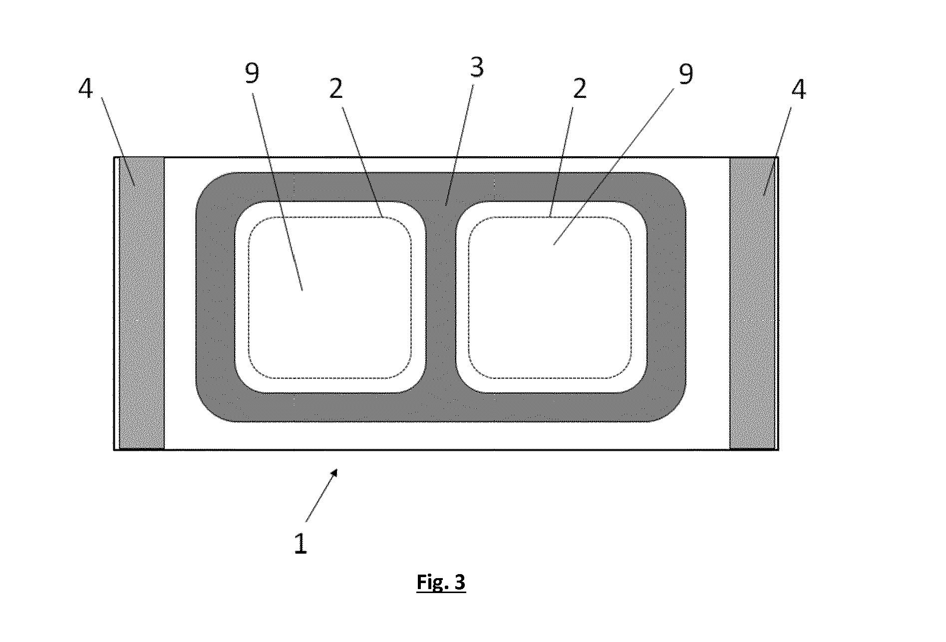
[0043]The present invention is related to a flowpack 1 enclosing a tray 5 comprising one or more cavity(ies), the film 6 forming said flowpack 1 being sealed against said tray 5 and forming a lid closing the individual cavity(ies) 9, said lid being part of the initial film of the flowpack.

[0044]Such flowpack 1 presents several advantages in comparison with prior-art tray packaging. As a first advantage, there is no need for a secondary packaging, as the flowrap film 6 completely encloses the tray 5.

[0045]As a further advantage, the flowpack 1 of the invention can be easily produced on modified horizontal form fill and seal machines or thermoform fill seal machines.

[0046]For example, filled trays can be fed to an horizontal form fill seal machine, wherein the flowpack 1 is formed and sealed around the filled tray, the inner surface of the flowpack 1 being sealed in a subsequent step on the top surface of the tray, thereby closing the individual cavities.

[0047]Alternatively, it is also p


PUM


Abstract

The present invention is related to a flowpack comprising a cross-sealed film, said film comprising one or more polymeric layer(s), said flowpack enclosing a tray comprising one or more cavity(ies), the film forming said flowpack being sealed against said tray and forming a lid closing the cavity(ies) of said tray, said lid being part of the initial film of the flowpack.

Description


Claims


Application Information

Patent Timeline
Owner AMCOR FLEXIBLE KREUZLINGEN LTD
Why Eureka
Try Eureka