Electrical Transmission Line Repair Apparatus

a transmission line and repair technology, applied in the direction of metal working apparatus, overhead line/cable apparatus, manufacturing tools, etc., can solve the problems of difficult installation environment, difficult to install, and especially difficult with existing equipment in a dead end configuration

Active Publication Date: 2015-09-10
CLASSIC CONNECTORS
View PDF4 Cites 2 Cited by
  • Summary
  • Abstract
  • Description
  • Claims
  • Application Information

AI Technical Summary

Benefits of technology

In certain arrangements, there are two ends where different components work together like screws or bolts for holding things securely in place during use. These connections can also hold objects tight against them when they shouldn't get loose due to vibrations from external sources such as machinery.

Problems solved by technology

The technical problem addressed in this patented solution relates to improving upon the process of installing electricity transmitting wires during power-line repairs without making it harden over time. Current methods involve attaching tools directly onto the wire's surface, but they can also damage them if installed too close together. There needs to provide better ways to prepare and assemble these components while still being able to handle high loads safely when located underground.

Method used


Image

  • Electrical Transmission Line Repair Apparatus
  • Electrical Transmission Line Repair Apparatus
  • Electrical Transmission Line Repair Apparatus

Examples


Embodiment Construction

[0048]While this invention is susceptible of embodiment in many different forms, there is shown in the drawings and described herein in detail a specific embodiment with the understanding that the present disclosure is to be considered as an exemplification and is not intended to be limited to the embodiment illustrated.

[0049]It will be understood that like or analogous elements and / or components, referred to herein, may be identified throughout the drawings by like reference characters. In addition, it will be understood that the drawings are merely schematic representations of the invention, and some of the components may have been distorted from actual scale for purposes of pictorial clarity.

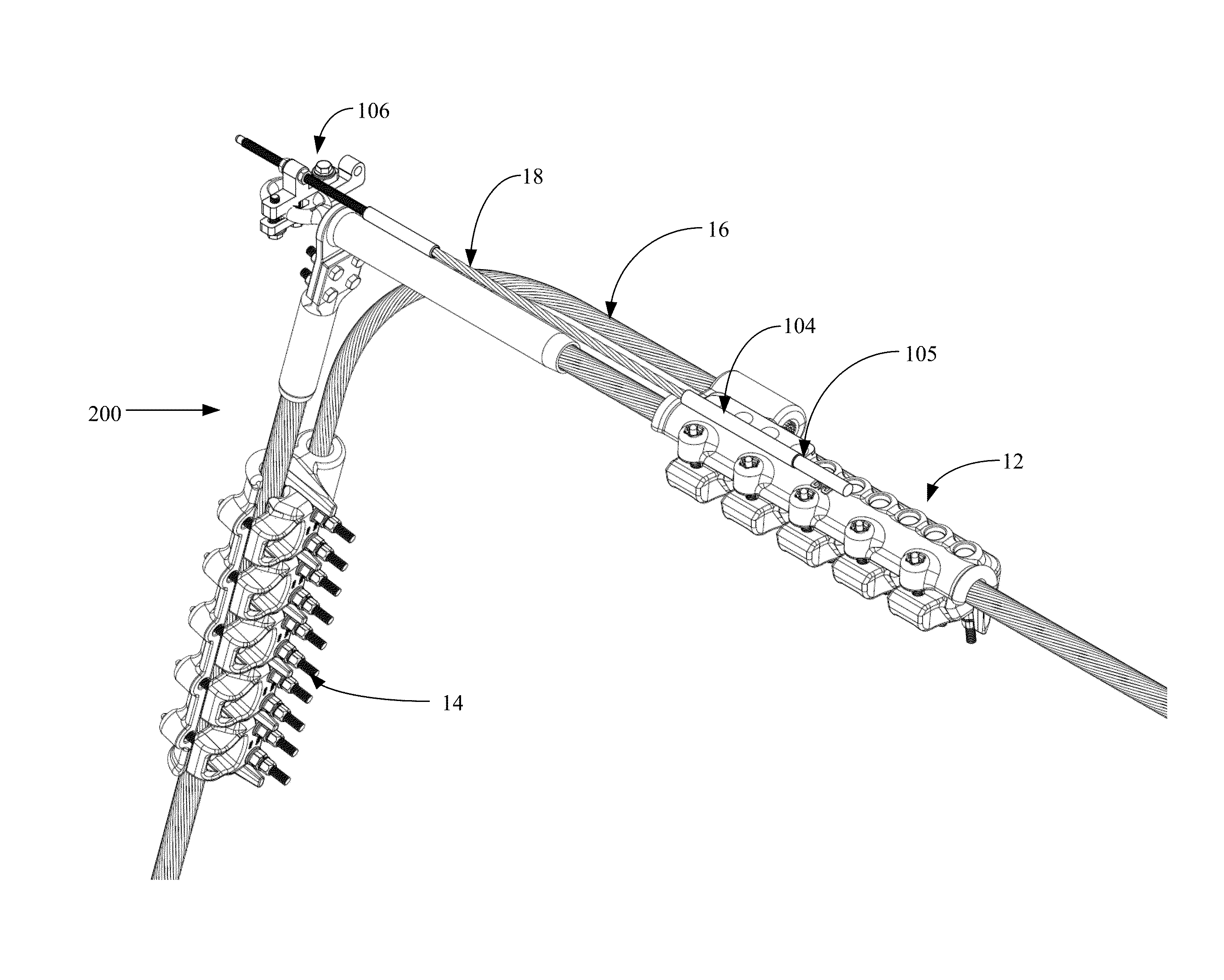
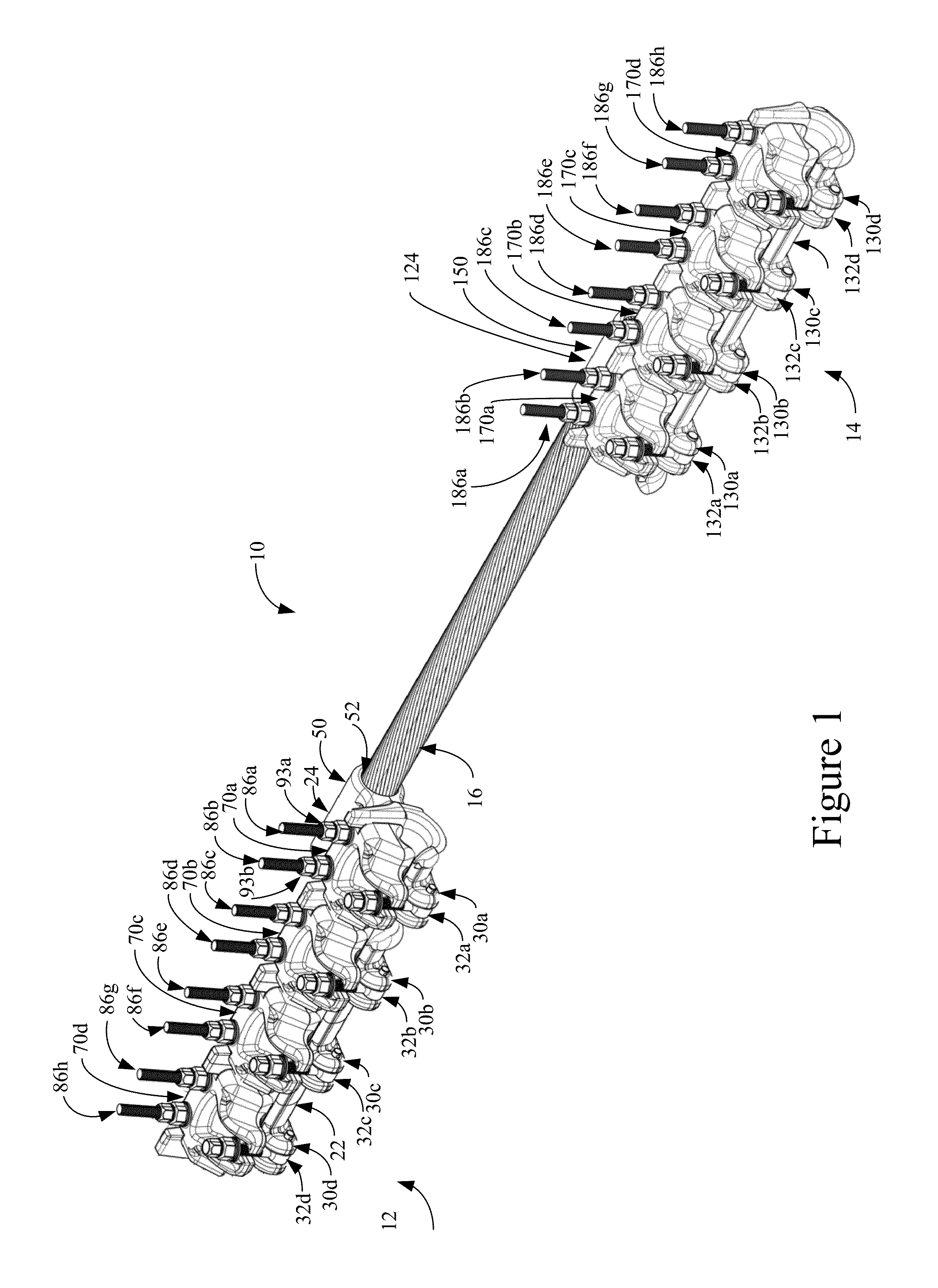
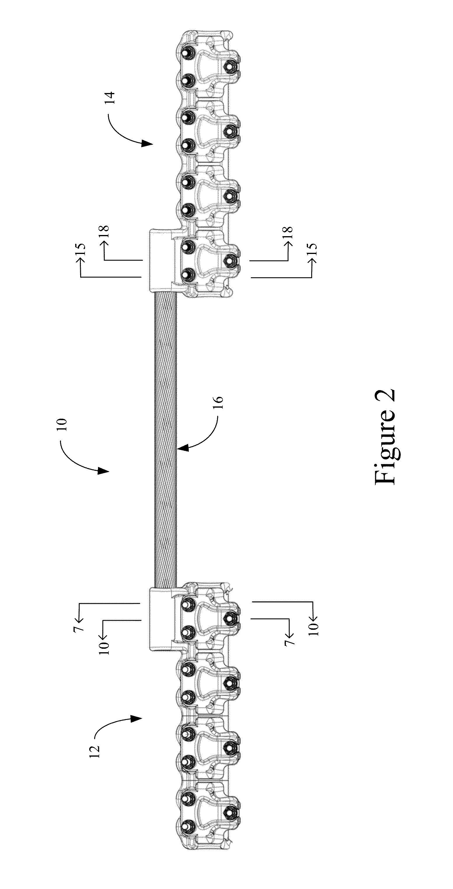
[0050]Referring now to the drawings and in particular to FIGS. 1 and 2, the electrical transmission line repair apparatus 10 is shown as including first end section 12, second end section 14 (FIG. 2 only) and link member 16. The apparatus 10 is configured for use in association with existing e


PUM

PropertyMeasurementUnit
Diameteraaaaaaaaaa

Abstract

An electrical transmission line repair apparatus comprising a first end section, a second end section and a link member. The first and second end sections are spaced apart from each other and each configured to receive and releasably retain a conductor thereacross. The link member is positioned on one side of the first and second end sections, so that the first and second end sections can be coupled to a conductor on either side of a link member, suspension or other device from below, and without decoupling or de-energizing the transmission line. In addition, the installation of the same and the clamping can be achieved from below the conductor upon positioning. That is, the link member or members do not straddle the transmission line, requiring dismantling of the dead end configuration, or the disassembly of the link member from the first and second end section.

Description


Claims


Application Information

Patent Timeline
Owner CLASSIC CONNECTORS
Why Eureka
Try Eureka