Video processing device and video processing method
- Summary
- Abstract
- Description
- Claims
- Application Information
AI Technical Summary
Benefits of technology
Problems solved by technology
Method used
Image

Examples
first embodiment
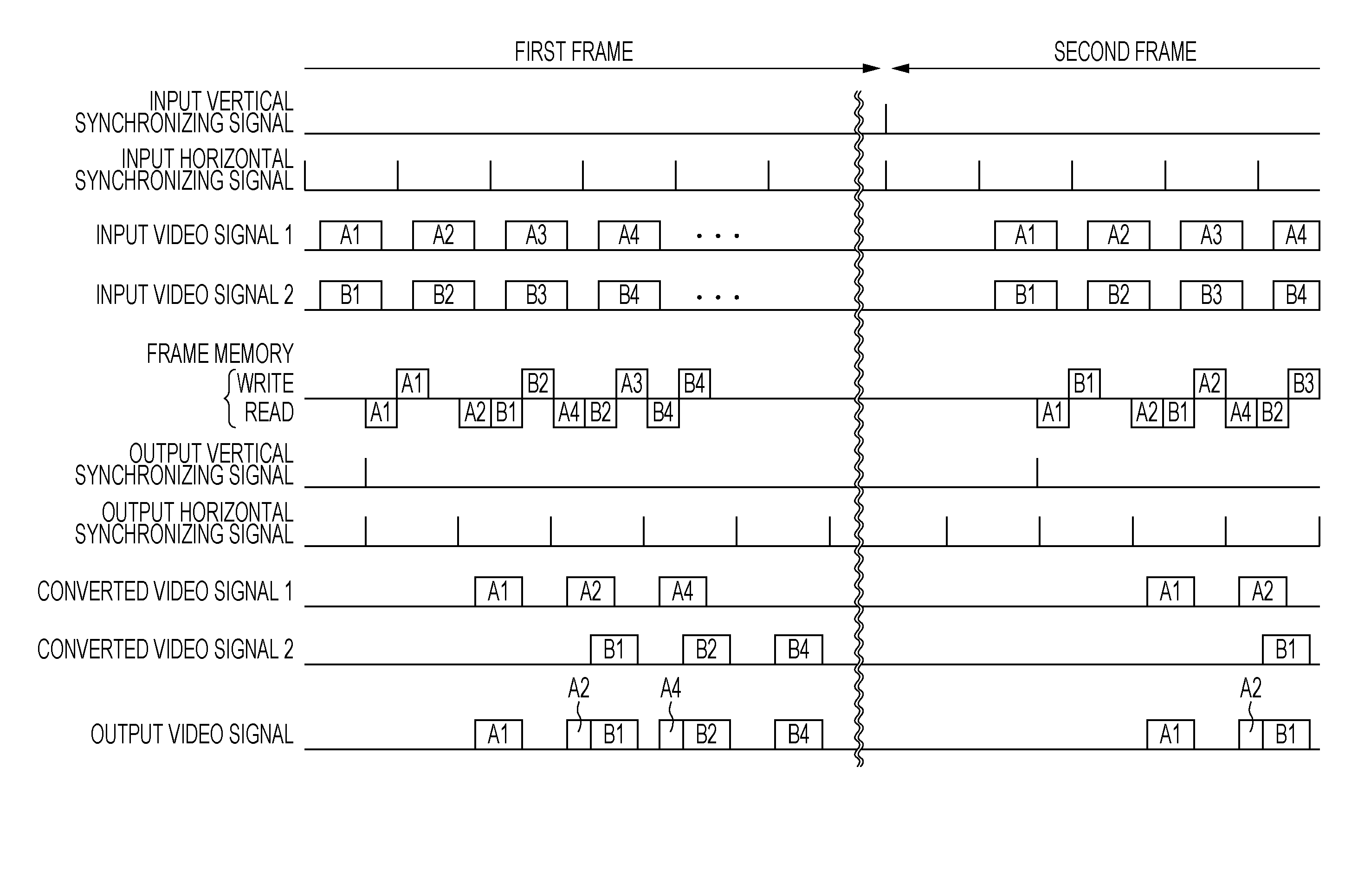
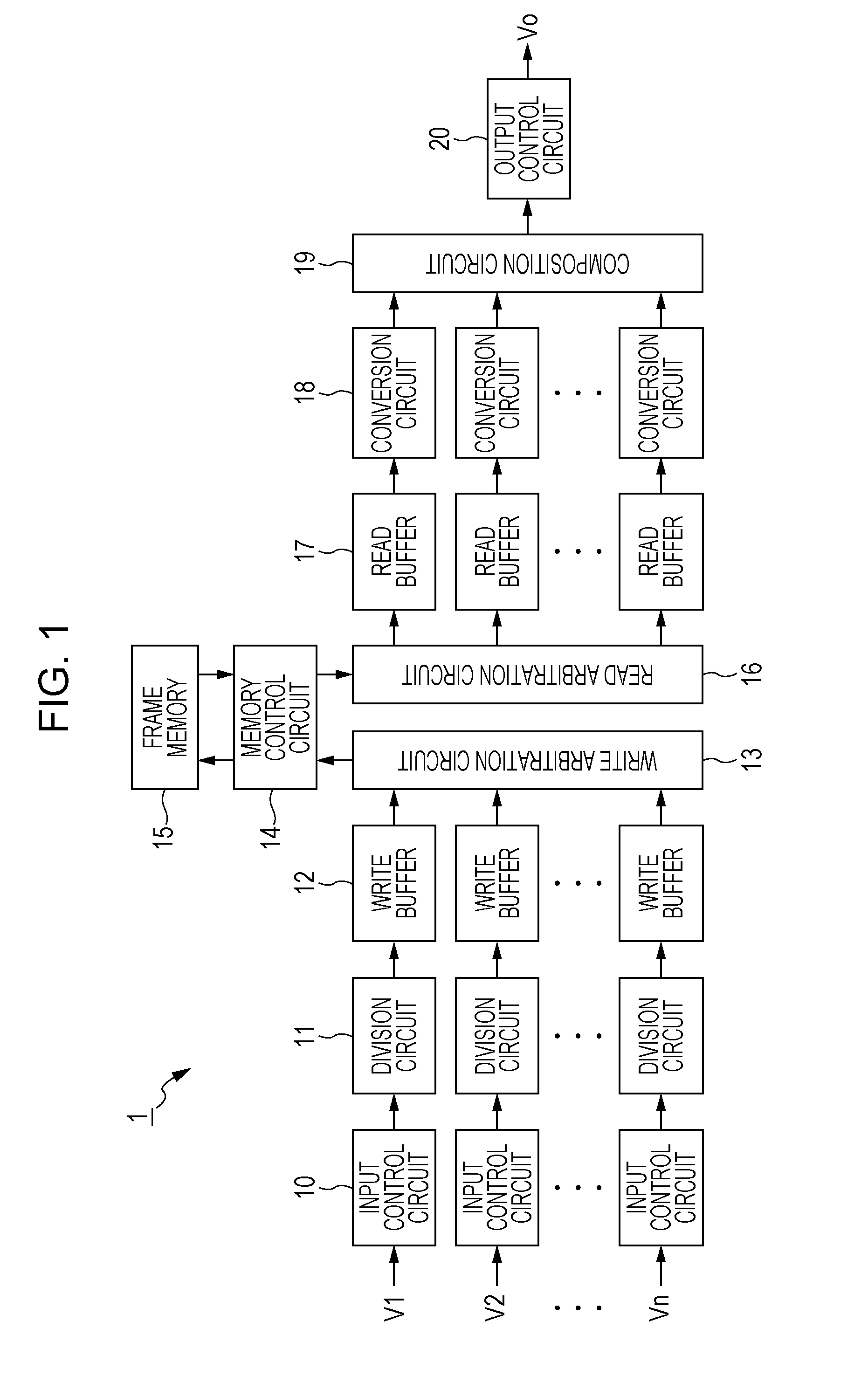
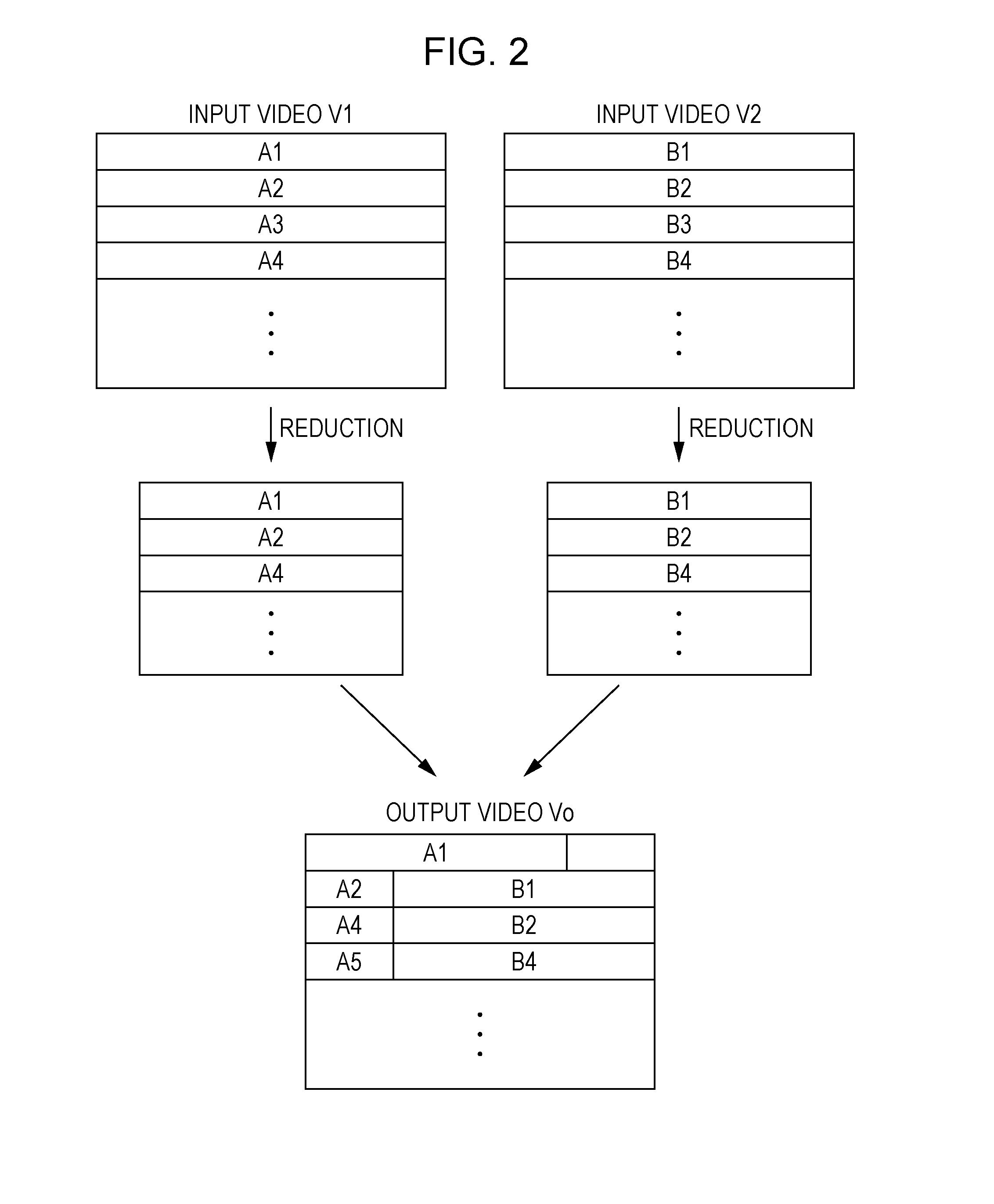
[0037]FIG. 1 is a block diagram showing a configuration of a video processing device according to a first embodiment of the present invention. A video processing device 1 shown in FIG. 1 includes n (n is an integer of 2 or more) input control circuits 10, n division circuits 11, n write buffers 12, a write arbitration circuit 13, a memory control circuit 14, a frame memory 15, a read arbitration circuit 16, n read buffers 17, n conversion circuits 18, a composition circuit 19 and an output control circuit 20.
[0038]To the video processing device 1, n input videos V1 to Vn are input. The video processing device 1 includes the n input control circuits 10, the n division circuits 11, the n write buffers 12, the n read buffers 17 and the n conversion circuits 18, correspondingly to the n input videos V1 to Vn. A circuit corresponding to an i-th (i is an integer from 1 to n) input video Vi is referred to as an i-th circuit below. The video processing device 1 composites the input videos V1 t
second embodiment
[0055]A video processing device according to a second embodiment of the present invention has the same configuration as that of the video processing device according to the first embodiment (FIG. 1). Description will be given below for differences from the first embodiment.
[0056]FIG. 5 is a view showing division of input frames in the video processing device according to the second embodiment of the present invention. In FIG. 5, L represents a left half of data for a single row and R represents a right half of data for a single row. In the present embodiment, the i-th division circuit 11 divides input frames included in the input video Vi into left-half data and right-half data. Further, the i-th division circuit 11 outputs one of the left-half data and the right-half data for an odd-numbered frame and outputs the other of the left-half data and the right-half data for an even-numbered frame.
[0057]FIG. 6 is a timing chart of the video processing device according to the present embodime
third embodiment
[0059]A video processing device according to a third embodiment of the present invention has the same configuration as that of the video processing device according to the first embodiment (FIG. 1). Description will be given below for differences from the first embodiment.
[0060]FIG. 7 is a view showing division of input frames in the video processing device according to the third embodiment of the present invention. In FIG. 7, o represents data in an odd-numbered column and e represents data in an even-numbered column. In the present embodiment, the i-th division circuit 11 divides input frames included in the input video Vi into data in an odd-numbered column and data in an even-numbered column. Further, the i-th division circuit 11 outputs one of the data in the odd-numbered column and the data in the even-numbered column for an odd-numbered frame and outputs the other of the data in the odd-numbered column and the data in the even-numbered column for an even-numbered frame.
[0061]FIG
PUM
 Abstract
Description
Claims
Application Information
 - R&D Engineer
- R&D Manager
- IP Professional
- Industry Leading Data Capabilities
- Powerful AI technology
- Patent DNA Extraction
Browse by: Latest US Patents, China's latest patents, Technical Efficacy Thesaurus, Application Domain, Technology Topic.
© 2024 PatSnap. All rights reserved.Legal|Privacy policy|Modern Slavery Act Transparency Statement|Sitemap